User Guide
Nodegrid Serial Console™
Nodegrid Services Router™
Nodegrid Bold SR™
Nodegrid Manager™
This document supports versions 4.0.x.
U.S. Notification
WARNING: Changes or modifications to this unit not expressly approved by the party responsible for compliance could void the user’s authority to operate the equipment.
NOTE: This equipment has been tested and found to comply with the limits for a Class A digital device, pursuant to Part15 of the FCC Rules. These limits are designed to provide reasonable protection against harmful interference when the equipment is operated in a commercial environment. This equipment generates, uses and can radiate radio frequency energy and, if not installed and used in accordance with the instruction manual, may cause harmful interference to radio communications. Operation of this equipment in a residential area is likely to cause harmful interference, in which case the user will be required to correct the interference at his/her own expense.
Canadian Notification
This Class A digital apparatus complies with Canadian ICES-003.
Cet appareil numérique de la classe A est conforme à la norme NMB-003 du Canada.
European Union Notification
Note: This is a class A product. In a domestic environment, this product may cause radio interference in which case the user may be required to take adequate measures.
Japan Notification

All other marks are the property of their respective owners. This document may contain confidential and/or proprietary information of ZPE Systems, Inc., and its receipt or possession does not convey any right to reproduce, disclose its contents, or to manufacture or sell anything that it may describe. Reproduction, disclosure, or use without specific authorization from ZPE Systems, Inc. is strictly prohibited.
©2019 ZPE Systems, Inc. All rights reserved.
Table of Contents
IntroductionProduct OverviewNodegrid Serial ConsoleNodegrid Serial Console - S SeriesNodegrid Serial Console - R SeriesNodegrid Serial Console - T SeriesNodegrid Services RouterNodegrid Services RouterNodegrid Services Router Expansion ModulesExpansion Module Compatibility ChartNodegrid Bold SRNodegrid ManagerInstallation Hardware InstallationWhat's in the Box?Installation of Modules for Nodegrid Services RouterRack MountingNetwork ConnectionConnecting Power Cord(s)Connecting Target DevicesConnecting Serial Target DevicesConnecting IP Target DevicesConnecting to a NodegridConnection via Console PortConnecting via ETH0Connection via Wi-FiConnection via KVM PortNodegrid Manager InstallationCreating a Virtual Machine - VMWareInstalling Nodegrid ManagerInitial Network ConfigurationIdentify Current IP AddressIdentify Current IP Address - WebUIIdentify Current IP Address - CLIDefine Static IP AddressDefine Static IP Address - Web UIDefine Static IP Address - CLIInterfacesWebUICLIShellAPIDevice AccessDevice SessionsDevice Sessions - Web UIDevice Sessions - CLIDevice InformationDisplay Device Information - Web UIDisplay Device Information - CLIDevice ViewsTable ViewTree ViewNode ViewMap ViewImage ViewSearchDevice SearchGlobal SearchDevice Management (Managed Devices)Configuration of Managed DevicesSerial DevicesConfigure Serial Devices - WebUIConfigure Serial Devices - CLIService Processor DevicesAdd Service Processor Devices - WebUIAdd Service Processor Devices - CLIDevices with SSHAdd Devices with SSH - WebUIAdd Devices with SSH - CLIConsole ServersAdd Console Servers - WebUIAdd Console Server Ports - WebUIAdd Console Servers - CLIAdd Console Server Ports - CLIKVM SwitchesAdd KVM Switches - WebUIAdd KVM Switch Ports - WebUIAdd KVM Switches - CLIAdd KVM Switch Ports - CLIRack PDU's Rack PDUs - WebUIAdd Rack PDU - CLICisco UCSAdd Cisco UCS - WebUIAdd Cisco UCS - CLINetappAdd Netapp - WebUIAdd Netapp - CLIInfraboxAdd Infrabox - WebUIAdd Infrabox - CLIVirtual MachinesAdd VMWare Virtual Machines - WebUIAdd VMWare Virtual Machines - CLIAdd KVM Virtual Machines - WebUIAdd KVM Virtual Machines - CLIAuto-DiscoveryAuto Discovery of Console Server and KVM Switch PortsAuto Discovery of Console Server and KVM Switch ports - WebUIAuto Discovery of Console Server and KVM Switch ports - CLIAuto Discovery of Network DevicesAuto Discovery of Network Devices - WebUIAuto Discovery of Network Devices - CLIAuto Discovery of Virtual MachinesAuto Discovery of Virtual Machines - WebUIAuto Discovery of Virtual Machines - CLIAuto Discovery of DHCP ClientsAuto Discovery of DHCP Clients - Web UIAuto Discovery of DHCP Clients - CLIDevice SettingsHostname DetectionConfigure Hostname DetectionGlobal Settings for Hostname DetectionCreate a Probe or MatchMulti SessionsBreak SignalEscape SequencesDisable User Authentication SSH / Telnet PortBinary SocketIP AliasesLocationWeb URLIconModeExpirationDevice State DetectionSerial DevicesIP DevicesRun Custom Scripts on Device Status ChangeData LoggingEvent LoggingAlert Strings and Custom ScriptsCustom FieldsCommands and Custom CommandsTree View SettingsDevice TypesPreferencesPower Menu PreferencesSession PreferencesTrackingOpen SessionsEvent ListSystem UsageDiscovery LogsNetwork StatisticsDevice StatisticsSchedulerSystemLicensesSystem PreferencesAddress LocationSession Idle TimeoutLogin logo imageLogin BannerUtilization RateConsole PortPower SuppliesNetwork Boot (PXE)Date and TimeLoggingCustom FieldsDial-Up System MaintenanceShutdown and RebootSoftware UpgradeFactory ResetSystem Configuration ChecksumLoad System CertificateNetwork ToolsBackup and RestoreSave SettingsRestore SettingsNetworkSettingsHostname and Domain NameNetwork FailoverIP ForwardingLoopback AddressNetwork Connection ConfigurationBonding InterfacesEthernet InterfacesMobile Broadband GSM InterfaceVLAN InterfaceWIFI InterfaceWIFI Access PointWIFI ClientWIFI SettingsBridge InterfaceAnalog Modem InterfaceStatic RoutesManual HostnamesDHCP ServerNetwork Switch ConfigurationSwitch InterfacesVLAN ConfigurationUntagged/Access PortsTagged/Trunk PortsBackplane PortsVPNSSL VPNSSL VPN Client SSL VPN SERVERIPSEC VPNAuthentication Methods Pre-shared Keys RSA Keys X.509 Certificates Connection Scenarios Host to Host Host to Site Site to Site Host to Multi Site Site to Multi Site Configuration of IPSec AuthenticationLocal AccountsManage Local UsersHash Format PasswordPassword RulesGroupsManage GroupsCreate a User GroupAdd local users to a groupAssign system permissions and settings to a groupAssign external groupsAssign device permissionsAssign power outlet permissionsExternal Authentication ProviderLDAP and Active DirectoryTACACS +RADIUSKerberosSecurityFirewallServicesActive ServicesManaged DevicesIntrusion PreventionSSHWeb ServiceCryptographic ProtocolsCloudPeers OverviewCloud SettingsEnable CloudAutomatic EnrollmentLicense PoolPeer ManagementAuditing SettingsData LoggingEventsDestinationsFileSyslogSNMP TrapEmail NotificationMonitoringCustomizing a Monitoring TemplateSNMP TemplateIPMI Discovery TemplateEnabling MonitoringDashboardExploring Data PointsCreating a VisualizationLine ChartsArea ChartsCreating a DashboardInspecting a DashboardApplicationsDocker ApplicationsDocker ImagesDocker ContainersApplication LinksNetwork Function VirtualisationAppendixTechnical SupportSubmit a Support TicketUpdates and PatchesConfiguring Virtual Serial Port (vSPC) on VM ServersDC PowerFundamentalsCase of -48VDC supply Case of +48VDC supplyAC PowerSerial Port PinoutSafety Quick Install Guide RoHS Data PersistencySoft RemovalHard Removal - Secure EraseCredits
Introduction
The Nodegrid 4.0 User manual covers the Nodegrid Platform version 4.0 and the supporting units like the Nodegrid Serial Console Series, Nodegrid Services Router and the Nodegrid Bold SR.
Product Overview
Nodegrid Serial Console
Nodegrid Serial Console product line consolidates and manages attached devices via Serial Port Connection including servers, network routers and switches, storage, PDUs, UPSs, and any other device with a serial port.
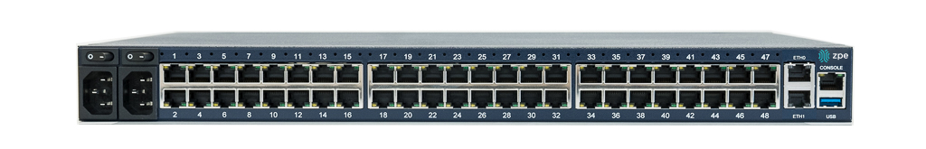
Nodegrid Serial Console - S Series
NODEGRID SERIAL CONSOLE (S Series) is made to fit any modern and legacy mixed environment. With auto-sensing ports, you can use the S Series Console Servers within any environment whether using straight through cables or with legacy adapters.
- Auto Switching (Cisco or Legacy Pin-out)
- 16/32/48 Serial Ports
- Additional USB ports
- Factory Upgradable CPU and RAM
- 1U 19" Rack Standard Unit
- Single AC, Dual AC , and Dual DC
Hardware Specifications
| Item | Description |
|---|---|
| CPU | Intel x86_64 dual core CPU |
| Memory & Storage | 4 GB of DDR3 DRAM, 32 GB mSATA SSD |
| Interfaces | 2 Gigabit (10/100/1000BT) Ethernet interfaces on RJ45 or 2 SFP+ Fiber interfaces compatible with 1GB / 2.5GB / 10GB modules 16, 32, 48 RS-232 serial ports on RJ45 @ 230,400 bps max/port. 1 RS-232 serial console port on RJ45 1 USB 3.0 Host,1 USB 2.0 Host and 12 USB 2.0 Hosts on Type A connector 1 HDMI |
| Power | Single/Dual AC 100-240 VAC, 50/60 Hz Dual DC: 40-63 VDC Power consumption 45 W typical |
| Physical | Front-Rear mounting brackets Size (L x W x H): 443 x 312 x 43 mm (17.4 x 12.3 x 1.7 in), 1U Weight: 4.9 kg (10.8 lb), depending on options Front-to-Back or Back-to-Front Fans (Swappable) |
| Environmental | Operation: 0 to 50° C (32 to 122° F), 20-90% RH, non-cond. Storage: -20 to 67° C (-4 to 153° F), 10-90% RH, non-cond. |
Interfaces Front
| Port | Description |
|---|---|
| HDMI | HDMI Interface |
| USB | USB 2.0 Port |
| PWR | Power LED |
| SYS | System LED |
| RST | Reset button : <10s system reset, >10s configuration factory reset and system reset |
| FAN | Fan's |
| USB | 1 x USB 2.0 Port, 12 x USB 1.1 Ports |
Interfaces Back
| Port | Description |
|---|---|
| Power | Single or Dual Power Sockets |
| Serial | Serial Interfaces |
| ETH0/SFP0 | Network Interface |
| ETH1/SFP1 | Network Interface |
| Console | Console MGMT Interface |
| USB | 1 x USB 3.0 |
Nodegrid Serial Console - R Series
NODEGRID SERIAL CONSOLE (R Series) is made to fit into major hardware environments like Cisco, Arista, Dell, Palo Alto Networks, and Juniper. R Series Serial Consoles are perfect for retrofits and to upgarde Rack Standards of existing builds.
- For Cisco Pin-out Devices
- 16/32/48/96 Serial Ports
- 1U 19" Rack Standard Unit
- Single AC, Dual AC , and Dual DC
Hardware Specifications
| Item | Description |
|---|---|
| CPU | Intel Atom x86_64 dual core @ 1.75 GHz CPU |
| Memory & Storage | 4 GB of DDR3 DRAM, 32 GB mSATA SSD |
| Interfaces | 2 Gigabit (10/100/1000BT) Ethernet interfaces on RJ45 or 2 SFP+ Fiber interfaces compatible with 1GB / 2.5GB / 10GB modules 16, 32, 48, 96 RS-232 serial ports on RJ45 @ 230,400 bps max/port. 1 RS-232 serial console port on RJ45 1 USB 3.0 Host and 2 USB 2.0 Hosts on Type A connector 1 HDMI |
| Power | Single/Dual AC 100-240 VAC, 50/60 Hz Dual DC: 40-63 VDC Power consumption 45 W (on 96 ports) |
| Physical | Front-Rear mounting brackets Size (L x W x H): 443 x 312 x 43 mm (17.4 x 12.3 x 1.7 in), 1U Weight: 4.9 kg (10.8 lb), depending on options |
| Environmental | Operation: 0 to 50° C (32 to 122° F), 20-90% RH, non-cond. Storage: -20 to 67° C (-4 to 153° F), 10-90% RH, non-cond. |
Interfaces Front
| Port | Description |
|---|---|
| HDMI | HDMI Interface |
| USB | 2 x USB 2.0 Port |
| PWR | Power LED |
| SYS | System LED |
| RST | Reset button : <10s system reset, >10s configuration factory reset and system reset |
Interfaces Back
| Port | Description |
|---|---|
| Power | Single or Dual Power Sockets |
| Serial | Serial Interfaces |
| ETH0/SFP0 | Network Interface |
| ETH1/SFP1 | Network Interface |
| Console | Console MGMT Interface |
| USB | USB 3.0 |
Nodegrid Serial Console - T Series
NODEGRID SERIAL CONSOLE (T Series) is made to fit into environments still utilizing legacy devices, and can be a direct replacement of the legacy console server.
- For Legacy Devices
- 16/32/48/96 Serial Ports
- 1U 19" Standard Unit
- Single AC, Dual AC , and Dual DC
Hardware Specifications
| Item | Description |
|---|---|
| CPU | Intel Atom x86_64 dual core @ 1.75 GHz CPU |
| Memory & Storage | 4 GB of DDR3 DRAM, 32 GB mSATA SSD |
| Interfaces | 2 Gigabit (10/100/1000BT) Ethernet interfaces on RJ45 or 2 SFP+ Fiber interfaces compatible with 1GB / 2.5GB / 10GB modules 16, 32, 48, 96 RS-232 serial ports on RJ45 @ 230,400 bps max/port. 1 RS-232 serial console port on RJ45 1 USB 3.0 Host and 2 USB 2.0 Hosts on Type A connector 1 HDMI |
| Power | Single/Dual AC 100-240 VAC, 50/60 Hz Dual DC: 40-63 VDC Power consumption 45 W (on 96 ports) |
| Physical | Front-Rear mounting brackets Size (L x W x H): 443 x 312 x 43 mm (17.4 x 12.3 x 1.7 in), 1U Weight: 4.9 kg (10.8 lb), depending on options |
| Environmental | Operation: 0 to 50° C (32 to 122° F), 20-90% RH, non-cond. Storage: -20 to 67° C (-4 to 153° F), 10-90% RH, non-cond. |
Interfaces Front

| Port | Description |
|---|---|
| HDMI | HDMI Interface |
| USB | 2 x USB 2.0 Port |
| PWR | Power LED |
| SYS | System LED |
| RST | Reset button : <10s system reset, >10s configuration factory reset and system reset |
Interfaces Back

| Port | Description |
|---|---|
| Power | Single or Dual Power Sockets |
| Serial | Serial Interfaces |
| ETH0/SFP0 | Network Interface |
| ETH1/SFP1 | Network Interface |
| Console | Console MGMT Interface |
| USB | USB 3.0 |
Nodegrid Services Router
The Nodegrid Services Router is a platform appliance designed for software-defined networking (SDN), out of band (OOB) management, DevOps, cellular failover, docker, SD-WAN, remote/branch offices, retail locations, and network function virtualization (NFV) capabilities.
Nodegrid Services Router
NODEGRID SERVICES ROUTER is a modular open platform appliance designed for software-defined networking (SDN), out of band (OOB) management, DevOps, cellular failover, docker, SD-WAN, remote/branch offices, retail locations, and network function virtualization (NFV) capabilities.
- Open Framework, Modular Services Router
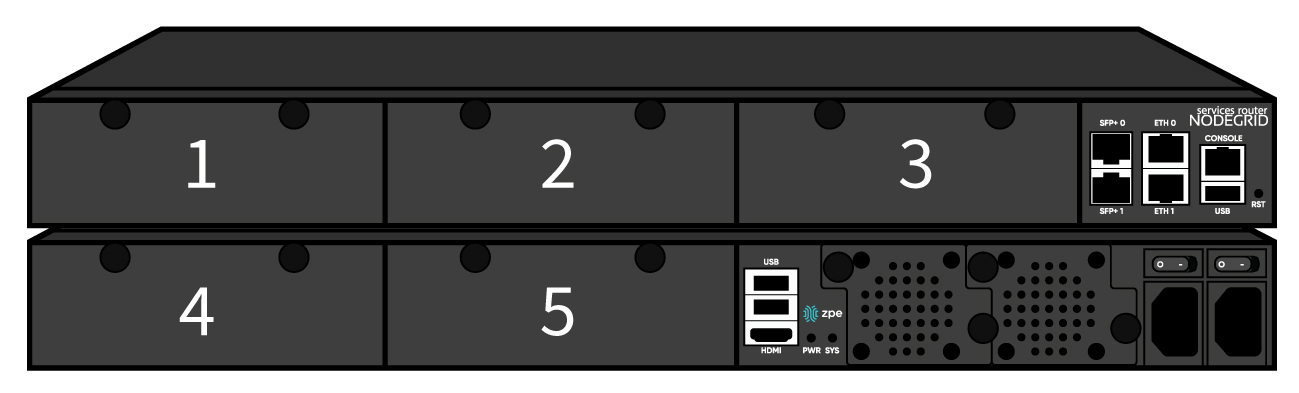
- Pluggable Expansion Modules - 5 slots available
- Modules for GbE, Serial, SFP+ 10GbE, PoE+, USB, M.2/SATA + Antenna, Storage, Extra Compute
- 1U 19" Standard Unit
- Separation of Control Plane and Data Plane
Hardware Specifications
| Item | Description |
|---|---|
| CPU | Intel Multi-core x86_64 CPU |
| Memory & Storage | 8 GB of DDR4 DRAM, 32 GB mSATA SSD (Factory Upgradeable) |
| Interfaces | 2 SFP+ Ethernet 2 Gigabit Ethernet 1 RS-232 serial console port on RJ45 1 USB 3.0 1 USB 2.0 1 HDMI |
| Power | Single/Dual AC 100-240 VAC, 50/60 Hz Dual DC: 36-75 VDC Power Consumption 90W typical |
| Physical | Front-Rear mounting brackets Size (L x W x H): 438 x 332 x 43mm (17.2 x 13.1 x 1.7 in), 1U Weight: 4.9 kg (10.8 lb), depending on options Air Exhaust or Air Intake Fans (Swappable) |
| Environmental | Operation: 0 to 45° C (32 to 113° F), 5-95% RH, non-cond. Storage: -20 to 67° C (-4 to 153° F), 10-90% RH, non-cond. |
Interfaces Front
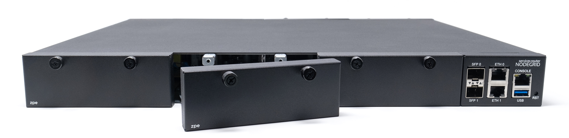
| Port | Description |
|---|---|
| Slot 1 | Slot for Module |
| Slot 2 | Slot for Module |
| Slot 3 | Slot for Module |
| SFP+ 0 | Network Interface |
| SFP+ 1 | Network Interface |
| ETH0 | Network Interface |
| ETH1 | Network Interface |
| Console | Console MGMT Interface |
| USB | USB 3.0 |
| RST | Reset button : <10s system reset, >10s configuration factory reset and system reset |
Interfaces Back
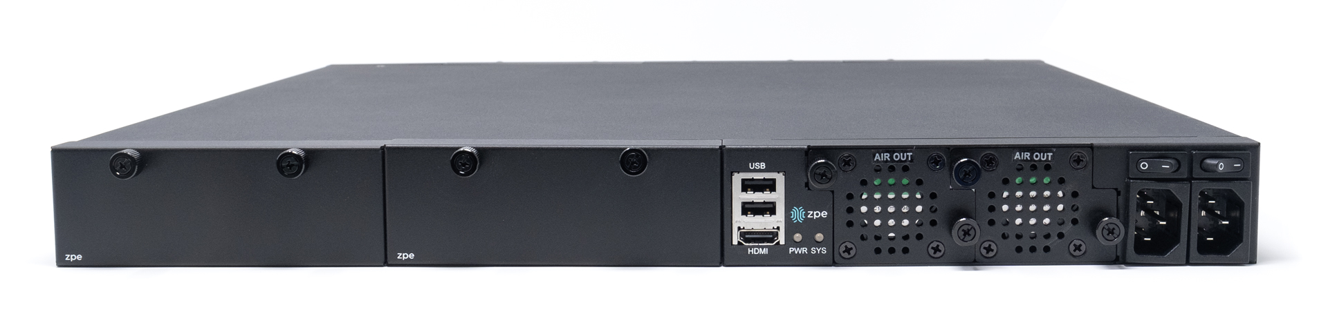
| Port | Description |
|---|---|
| Slot 4 | Slot for Module (depending on the Model) |
| Slot 5 | Slot for Module (depending on the Model) |
| USB | 2 x USB 2.0 Port |
| HDMI | HDMI Interface |
| PWR | Power LED |
| SYS | System LED |
| FAN | Fan's |
| Power Socket | Dual Power Sockets |
| Power | Single or Dual Power Sockets |
Nodegrid Services Router Expansion Modules
Nodegrid Services Router has up to five slots for modules that provides extreme flexibility for function expansion.
| Module | Picture | Specification |
|---|---|---|
| 16-Port 1GbE | 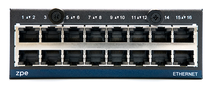 | 1000BASE-T Cat5e or better |
| 8-Port SFP+ 10GbE | 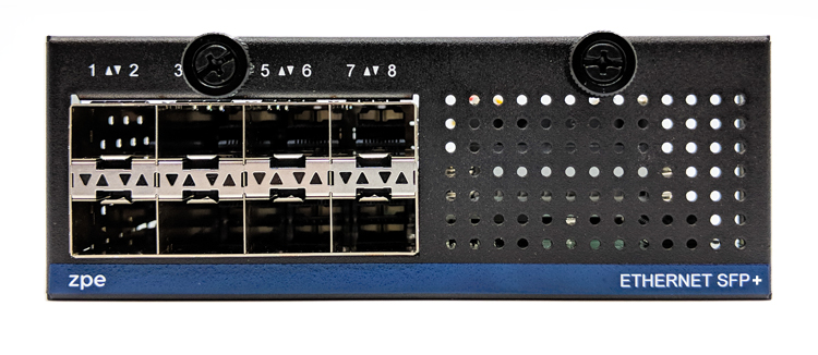 | Supports all SFP+ Modules |
| 8-Port PoE+ | 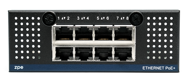 | 25.5W max power per port Total max 150W PoE+ available Configurable power budget |
| 16-Port Serial | 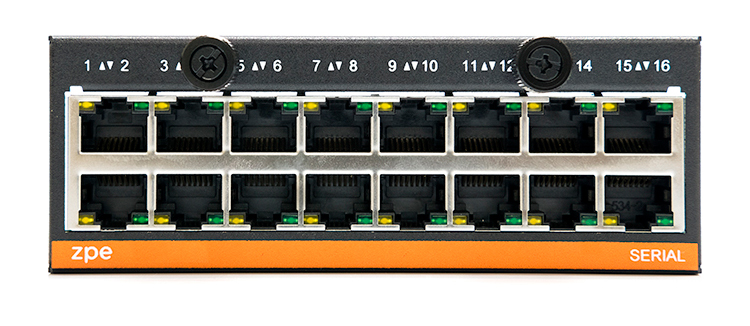 | RJ45 Serial Rolled port max 230,400 bps |
| 16-Port USB | 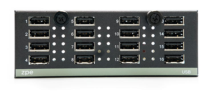 | USB 2.0 interfaces Type A |
| M.2 Cellular + Antenna | 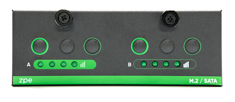 | For upto 2x 4G/LTE modems |
| M.2 SATA | | For upto 2x mSATA storage modules |
| Storage | 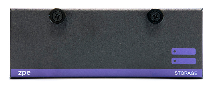 | For 2.5" SATA (HDD/SDD) storage |
| Compute | 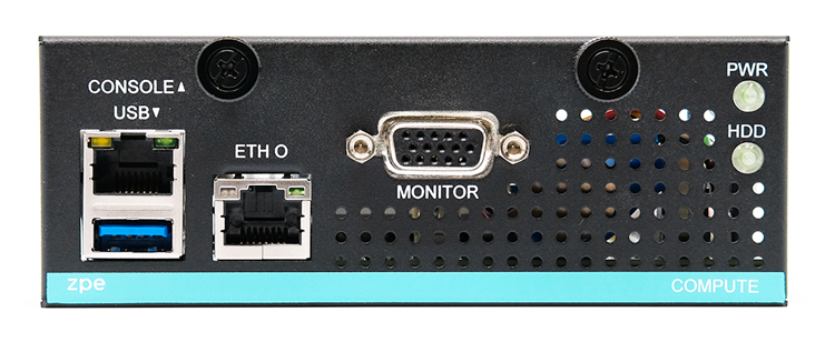 | Compute module (server on a card), provides independent compute capabilities. |
Expansion Module Compatibility Chart
| Expansion Card | Slot 1 | Slot 2 | Slot 3 | Slot4 | Slot5 |
|---|---|---|---|---|---|
| 16-Port GbE Ethernet | ✔ | ✔ | ✔ | Secure Isolated Mode ** | Secure Isolated Mode ** |
| 16-Port Serial | ✔ | ✔ | ✔ | ✔ | ✔ |
| 16-Port USB | ✔ | ✔ | ✔ | ✔ | ✔ |
| M.2 Cellular / Wi-Fi | ✔ | ✔ | ✔ | ✔ | ✔ |
| 8-Port SFP+ | ✔ | ✔ | ✔ | Secure Isolated Mode ** | Secure Isolated Mode ** |
| 8-Port POE+ | ✔ | ✔ | ✔ | – | – |
| Compute | ✔ | ✔ | ✔ | Secure Isolated Mode ** | Secure Isolated Mode ** |
| Storage * | – | – | – | ✔ | ✔ |
| M.2 SATA * | – | – | – | ✔ | ✔ |
Note:
(*) The Nodegrid Services Router supports a maximum of 2 SATA drives, which can be divided into 2 Storage cards or in one M.2 SATA card
(**) The Secure Isolated Mode allows for the managment of the cards as if they would be located in a normal Slot, but the network traffic is isolated from anyother slot.
Nodegrid Bold SR
Nodegrid Bold SR is an open platform appliance designed for secure access and control over remote and IoT devices at the EDGE of your network. Bold SR supports cellular failover, Network Function Virtualization (NFV) and Software Defined Networking with a focus on SD-WAN.
- 1U high, compact size, high processing power
- Ideal for Software Defined Networking
- Network Function Virtualization
- Cellular failover
- Wi-Fi hotspot & client
- Multi Interfaces
Hardware Specifications
| Item | Description |
|---|---|
| CPU | Intel Multi-core x86_64 CPU |
| Memory & Storage | 4 GB of DDR3 DRAM, 32 GB mSATA SSD (Upgradeable) |
| Interfaces | 1 Gigabit (10/100/1000BT) Ethernet interfaces on RJ45 4 Gigabit (10/100/1000BT) Ethernet interfaces on RJ45 with Built-in Switch 8 RS-232 serial ports on RJ45 1 RS-232 console port on RJ45 USB 3.0 Host on Type A 2 USB 2.0 Hosts on Type A 1 Wi-Fi – optional 2 Cellular Slots with Dual SIM – Optional 1 VGA port |
| Power | 12 VDC via external 100–240 VAC, 50/60 Hz adapter 12 VDC via external 48 VDC adapter Power consumption 25 W typical |
| Physical | Front-Rear mounting brackets Size (L x W x H): 142 x 201 x 44 mm (5.5 x 7.9 x 1.73 in) Weight: 1.2 kg (2.6 lb) |
| Environmental | Operation: -20°C to 50°C (-4 to 122° F), 20-90% RH, non-cond. Storage: -20 to 67° C (-4 to 153° F), 10-90% RH, non-cond. |
Interfaces Front

| Port | Description |
|---|---|
| Channel A | Signal Strength indicator for Channel A |
| Channel B | Signal Strength indicator for Channel B |
| Console | Console MGMT Interface |
| PWR | Power LED |
| SYS | System LED |
| Power Switch | Power Switch |
| RST | Reset button : <10s system reset, >10s configuration factory reset and system reset |
Interfaces Back
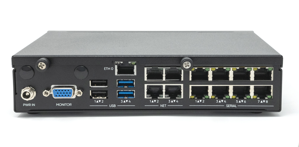
| Port | Description |
|---|---|
| PWR IN | Power Socket for external Power Supply |
| Monitor | VGA Interface |
| ETH0 | Network Interface (WAN) |
| USB | 2 x USB 2.0 Port 2 x USB 3.0 Port |
| ETH1 | Network Interface (NET) |
| ETH2 | Network Interface (NET) |
| ETH3 | Network Interface (NET) |
| ETH4 | Network Interface (NET) |
| Serial | Serial Interfaces 1-8 |
Nodegrid Manager
Nodegrid Manager provides you with a unified solution to control compute, network, storage, and smart power assets.
Hardware Requirements
| Item | Description |
|---|---|
| CPU | min. 2 x Intel Multi-core x86_64 CPU |
| Memory & Storage | 4 GB RAM, min 32 GB HDD |
| Interfaces | min 1 Gigabit Ethernet interface |
| Supported Hypervisors | VMWare ESX, Linux KVM, Oracle Virtualbox -- Linux OS |
Installation
Hardware Installation
Please refer to Appendix - Quick Install Guide provided along with the unit in the box for quick instructions on how to start your box.
What's in the Box?
Each unit is shipped with multiple accessories. The below table lists the content of the box.
| Model | Mounting Brackets | Power Cables | Loop-Back Adapter | Console Adapter | Network Cable | QuickStart Guide & Safety Sheet |
|---|---|---|---|---|---|---|
| Nodegrid Serial Console - T Series | Yes | Yes | Legacy | Z000036 | Yes | Yes |
| Nodegrid Serial Console - R Series - TxxR | Yes | Yes | Cisco | Z000015 | Yes | Yes |
| Nodegrid Serial Console - S Series - TxxS | Yes | Yes | Legacy/Cisco | Z000015 Z000036 | Yes | Yes |
| Nodegrid Services Router | Yes | Yes | Legacy/Cisco | Z000014 Z000015 | Yes | Yes |
| Nodegrid Bold Services Router | No | External Power Supply | Legacy/Cisco | Z000014 Z000015 | Yes | Yes |
Installation of Modules for Nodegrid Services Router
The Nodegrid Services Router supports different modules. These need to be installed before the unit is powered up. The modules should be installed in an ESD protected environment, to avoid damage to any of the components. To install a card follow the following steps.
- Ensure that the Nodegrid Services Router is powered off
- Turn off the power supplies on the Nodegrid Services Router
- Unscrew the blanking panel which covers the slot in which the module should be installed
- Unbox the card and insert it into the appropriate slot
- Fix the card with the provided screw bolds
- The Nodegrid Services Router can now be turned on
Note: The blanking panel should be kept for later use. For thermal efficiency and safety, each unused slot needs to be covered with a blanking panel.
| Expansion Card | Slot 1 | Slot 2 | Slot 3 | Slot 4 | Slot 5 |
|---|---|---|---|---|---|
| 16-Port GbE Ethernet | ✔ | ✔ | ✔ | Secure Isolated Mode ** | Secure Isolated Mode ** |
| 16-Port Serial | ✔ | ✔ | ✔ | ✔ | ✔ |
| 16-Port USB | ✔ | ✔ | ✔ | ✔ | ✔ |
| M.2 Cellular / Wi-Fi | ✔ | ✔ | ✔ | ✔ | ✔ |
| 8-Port SFP+ | ✔ | ✔ | ✔ | Secure Isolated Mode ** | Secure Isolated Mode ** |
| 8-Port POE+ | ✔ | ✔ | ✔ | – | – |
| Compute | ✔ | ✔ | ✔ | Secure Isolated Mode ** | Secure Isolated Mode ** |
| Storage * | – | – | – | ✔ | ✔ |
| M.2 SATA * | – | – | – | ✔ | ✔ |
Note:
(*) The Nodegrid Services Router supports a maximum of 2 SATA drives, which can be divided into 2 Storage cards or in one M.2 SATA card
(**) The Secure Isolated Mode allows for the managment of the cards as if they would be located in a normal Slot, but the network traffic is isolated from anyother slot.
Rack Mounting
All units which are shipped with rack mounting brackets can be mounted to fit in the standard 19" rack. Two rack mounting brackets are provided in the box as outlined in Section (What is in the box). The remainder of this document will refer to "rack or cabinet" as "rack".
- Install the rack mounting brackets with provided screws (5 for each bracket) to the Nodegrid unit.
Note: Some units are actively cooled by fans, it is important these units are getting properly mounted into the rack, to ensure that the fans blow into the correct direction. The fan direction can be determined from the part number of the unit.
| Model | Part Number | Cooled | Air Flow | |
|---|---|---|---|---|
| Nodegrid Serial Console - T Series | NSC-Txx-xxxx-xxx | Passive | N/A | |
| Nodegrid Serial Console - R Series | NSC-TxxR-xxxx-xxx | Passive | N/A | |
| Nodegrid Serial Console - S Series | NSC-TxxS-xxxx-xxx-F | Active | Front-Back (air in) | 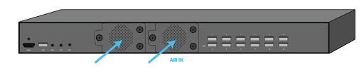 |
| Nodegrid Serial Console - S Series | NSC-TxxS-xxxx-xxx-B | Active | Back-Front (air out) | 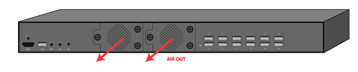 |
| Nodegrid Services Router | NSR-xxxx-xxx | Active | Front-Back (air out) | 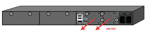 |
| Nodegrid Services Router | NSR-xxxx-xxx | Active | Back-Front (air in) |  |
| Nodegrid Bold Services Router | BSR-xx-xxxx | Passive | N/A |
- Place the unit into the allocated space in the rack.
- Secure the unit by tightening the appropriate rack screws (not provided).
Network Connection
Depending on the model and version the unit will either have a minimum of 2 copper ethernet ports or 2 SFP+ ports. Connect the desired network cables (CAT5e, CAT6, CAT6A) from your network switch port to any of the available network ports of the unit. For models with SFP+ ports install the SFP+ module before the unit is turned on and connect the appropriate cables.
Connecting Power Cord(s)
The Nodegrid unit includes one or multiple power supplies (AC or DC). Connect all the power supplies with appropriate cables to an available power source, like a Rack PDU. In case your unit is shipped with one power supply then no redundancy for a power failure is available. unit with two power supplies provides redundancy against power failures. Both power supplies should be connected to two independent power sources.
Note - Nodegrid Services Router with PoE: On the Nodegrid Services Router with PoE support, the 2nd power supply is used to provide power for the PoE feature and can not be used to provide redundancy for a power outage.
After all the power supplies are appropriately connected to a power source turn the power supplies on.
(See Appendix - DC Power for information on the DC power supply ports).
Connecting Target Devices
Connecting Serial Target Devices
Note: To avoid EMC issues use good quality network cable for all port connections.
The cabling and adapters that you may need to use between the unit serial ports and the serial devices’ console port will depend on their pinouts.
Latest serial devices such as routers, switches, and servers will have either a DB9, RJ45 or USB port as their console ports. See the manufacturer’s manual of your serial device console for the port pinout. In case of an RJ45 port console port, it is likely that it will use the Cisco-like pinout.
See table below for cabling you need to use depending on your unit serial ports and Serial Devices’ console port.
| Model | Port Type | Pinout | Device Port - RJ45 (Legacy) | Device Port - RJ45 (Cisco) | Device Port - DB9 | Device Port - USB |
|---|---|---|---|---|---|---|
| Nodegrid Serial Console - T Series | RJ45 | Legacy | CAT5e cable | CAT5e cable plus Z000039 crossover adapter | CAT5e cable plus Z000036 crossover adapter | USB |
| Nodegrid Serial Console - R Series | RJ45 | Cisco | - | CAT5e cable | CAT5e cable plus Z000015 crossover adapter | USB |
| Nodegrid Serial Console - S Series | RJ45 | Auto-Sensing (Legacy/Cisco) | CAT5e cable | CAT5e cable | CAT5e cable plus Z000015 crossover adapter | USB |
| Nodegrid Services Router | RJ45 | Cisco | - | CAT5e cable | CAT5e cable plus Z000015 crossover adapter | USB |
| Nodegrid Bold Services Router | RJ45 | Cisco | - | CAT5e cable | CAT5e cable plus Z000015 crossover adapter | USB |
If the serial device’s RJ45 does not have the Cisco-like pinout, or if you have any questions on connecting your serial device to the unit, please contact ZPE Systems Technical Support for assistance.
Connecting IP Target Devices
Note: To avoid EMC issues use good quality network cable for all port connections.
All IP based target device can be either directly connected to a network interface on a Nodegrid unit or through an existing network infrastructure. In case target devices are directly connected, standard network cables (CAT 5, CAT6, CAT6e) can be used for ethernet connections or appropriate fiber cables can be used.
Connecting to a Nodegrid
Connection via Console Port
Use the provided CAT5e and RJ45-DB9 Z000036 adapter/cable to communicate with the Nodegrid unit. Connect one end of the CAT5e cable to the Nodegrid console port. Connect the other end to the RJ45-DB9 adapter, and then plug it to your laptop or PC's DB9 COM port (if your laptop or PC does not have DB9 COM port, use a USB-DB9 adapter (not provided)).
Have a serial application (such as xterm, TeraTerm, Putty, SecureCRT) running on your laptop/PC to open a terminal session to that COM port (see the system information about the COM port to be used) with 115200bps, 8 bits, No parity, 1 stop bit, and no flow control settings.
Connecting via ETH0
The ETH0 interface is by default configured to listen to DHCP requests. In case no DHCP Server is available, the unit will use a default IP address of 192.168.160.10. The unit can be accessed using a browser on https://[DHCP ASSIGNED IP] or on https://192.168.160.10, alternatively, can the unit be accessed with an ssh client.
| Setting | Value |
|---|---|
| DHCP | enabled |
| fallback IP | yes |
| Default IP | 192.168.160.10/24 |
| Default URL | https://192.168.160.10 |
| Default ssh | ssh admin@192.168.160.10 |
Connection via Wi-Fi
The Nodegrid is pre-configured to act as a Wi-Fi hotspot in case an appropriate Wi-Fi device is connected. This can either be a built-in Wi-Fi module or a USB Wi-Fi adapter.
The Nodegrid will automatically be presenting a Wi-Fi network with the SSID Nodegrid. The default WPA Shared key is Nodegrid. The Nodegrid will not automatically provide an IP address to clients. Configure the client to have a valid IP address in the 192.168.162.1/24 range. The unit can now be accessed using a browser on https://192.168.162.1 or through ssh.
| Setting | Value |
|---|---|
| SSID | Nodegrid |
| WPA Shared key | Nodegrid |
| Default Network | 192.168.162.1/24 |
| Default URL | https://192.168.162.1 |
| Default ssh | ssh admin@192.168.162.1 |
Connection via KVM Port
The Nodegrid unit can be directly configured and managed through it's KVM interfaces. Connect a Monitor with an HDMI cable to the units HDMI interface.
The Nodegrid Bold SR provides a VGA port instead of an HDMI interface.
Note: HDMI to DVI-D adapters can be used and allow the connections of a DVI-D Monitor.
Connect a USB Keyboard and Mouse to the available USB ports.
Note: The keyboard and mouse need to be supported under Linux, Windows only devices are not supported. This limitation mostly affects devices which use a USB wireless dongle.
The login prompt will be presented.
Nodegrid Manager Installation
Nodegrid Manager software is installed from an ISO file. The installation procedure is a three-stage process:
- Creating a virtual machine
- Booting from the ISO file/CD in order to install the software
- Restarting and booting from the newly created virtual machine.
Minimum Requirements
- ESXi 4.1 or above
- 32 GB hard drive (connected through LSI Logic Parallel Controller)
- 4 GB memory (8GB recommended)
- 2 Network adapters (recommended E1000 adapters)
Creating a Virtual Machine - VMWare
- From the ESXi vSphere screen, click on Create a new virtual machine link
- For the virtual machine configuration, click on Create a new virtual machine and then click Next

- Choose an appropriate "Name" for your Nodegrid Manager virtual machine and select as "Guest OS family" Linux and "Guest OS version" Other Linux (64-Bit) then, click Next

- Select the data storage volume on which you wish to create for the new virtual machine, then click Next

- In the "Customize settings" screen, provide the following settings:
CPU: 2
Memory: 4GB
hard disk: 32GB
SCSI Controller:LSI Logic Parallel
network adapters: 2 of type E1000
click Next
Note: the values are minimum settings and should be adjusted as needed

- Click Finish to complete the configuration of the virtual machine on the ESXi server.

Installing Nodegrid Manager
To install your Nodegrid Manager software:
- Click on the Console tab from the summary screen of the virtual machine
- Turn on the power. The virtual machine will fail to boot since there is no operating system installed
- Click on the CD/DVD icon and select the location of Nodegrid Manager ISO file in your system
- Reboot the virtual machine by clicking on CTL-ALT-INSERT in the console area
- The virtual machine console server software will start with a boot prompt. At the boot prompt, you can hit ENTER or wait. The image will be decompressed and then loaded
- Once the image has booted, follow the instructions on the console. You must accept the EULA in order to proceed with the installation, type accept

- The installation process will copy the files into the virtual machine and automatically reboot the system in order to start Nodegrid Manager. Click ENTER to boot the image or wait for the image to boot automatically

- After booting the image, your new copy of Nodegrid Manager will be available and ready to be configured.

Initial Network Configuration
After the Nodegrid Platform is turned on, boot messages will be displayed, and the login prompt will be displayed.
The default administrator username is admin and the default password is admin. Admin users can access the Nodegrid Platform via a console port, through the web interface (HTTPS) or CLI (SSH). Other access methods can be enabled.
The superuser is root and the default password is root. The root user has SHELL access to the Linux OS, but not to the Web Interface.
By default, Nodegrid Platform is set up with DHCP IP configuration enabled.
Note: The Nodegrid Platform will respond on ETH0 at 192.168.160.10 if your DHCP server fails or is unavailable.
Identify Current IP Address
To identify the currently assigned IP address/es login to the Nodegrid Platform as admin user and navigate to the Network Connections screen.
Identify Current IP Address - WebUI
- Login as admin user with the default password admin
- Navigate to Network :: Connections
Identify Current IP Address - CLI
- Login as admin user with the default password admin
- display the current settings with
show /system/network_statistics/
Example Output:
[admin@nodegrid /]# show /settings/network_connections/name status type interface carrier state ipv4 address ipv6 address mac address description========== ========== ======== ========== ============= ================= =========================== ================= ===========BACKPLANE0 connected ethernet eth0 up 192.168.10.252/24 fe80::290:fbff:fe5b:72bc/64 00:90:fb:5b:72:bcETH0 connected ethernet backplane0 up 192.168.29.3/24 fe80::290:fbff:fe5b:72bd/64 00:90:fb:5b:72:bdhotspot not active wifi down
Define Static IP Address
- If no DHCP server is available on your network, or you want to change from dynamic to static IP, configure the network parameters.
Note: The below examples use IPv4 for communication. IPv6 is fully supported on the Nodegrid Platform and appropriate settings are available in the same menus.
Define Static IP Address - Web UI
- Navigate to Network:: Connections
- Click on the Interface which should be configured
- Provide the desired details
- Click on Save
Define Static IP Address - CLI
- Navigate to the desired network Interface
xxxxxxxxxx[admin@Nodegrid /]# cd settings/network_connections/ETH0/
- Configure the Network interface
xxxxxxxxxx[admin@Nodegrid ETH0]# set ipv4_mode=static[admin@Nodegrid ETH0]# set ipv4_address=<IP_ADDRESS> ipv4_bitmask=<BITMASK> ipv4_gateway=<GATEWAY>[admin@Nodegrid ETH0]# commit
Example:
xxxxxxxxxx[admin@Nodegrid /]# cd settings/network_connections/ETH0/[admin@Nodegrid ETH0]# set ipv4_mode=static[admin@Nodegrid ETH0]# set ipv4_address=10.0.0.10 ipv4_bitmask=24 ipv4_gateway=10.0.0.1[admin@Nodegrid ETH0]# showname: ETH0type: ethernetethernet_interface = eth0connect_automatically = yesset_as_primary_connection = noenable_lldp = noipv4_mode = staticipv4_address = 10.0.0.10ipv4_bitmask = 24ipv4_gateway = 10.0.0.1ipv4_dns_server =ipv4_dns_search =ipv6_mode = address_auto_configurationipv6_dns_server =ipv6_dns_search =[admin@Nodegrid ETH0]# commit
Follow the same steps for other interfaces as required.
Interfaces
WebUI
The Nodegrid platform can be accessed via its build in WebUI. The interface allows for full access to all target devices and configuration and management of the platform.
The Web UI supports all modern browsers with HTML5 support including mobile browsers. Regularly tested browsers include Internet Explorer 11, Edge, Chrome and Firefox.
The WebUI provides the following general structure
| Menu | Icon | Description |
|---|---|---|
| Access | The access menu provides easy access for all users to managed devices. It allows users with the appropriate permissions to start sessions, control power and review the device logging details | |
| Tracking | The tracking menu provides an overview of general statistics and system information, like system utilization and serial port statics beside others. | |
| System | The system's menu allows administrators to perform general administrative tasks on the Nodegrid Platform, for example, Firmware updates, backups and restores and licenses | |
| Network | The Network menu allows access and administration to all network interfaces and features | |
| Managed Devices | Through this menu can administrators add, configure and remove devices which should be managed through the Nodegrid platform | |
| Cloud | The Cloud menu allows administrators to administrate the Nodegrid Cloud feature | |
| Security | The Security menu provide configuration options which controls user access and general security of the Nodegrid platform | |
| Auditing | This menu allows administrators to administrate auditing levels and locations as well as some global logging settings. | |
| Dashboard | The Dashboard allows users and administrators to create and view dashboards and reports. | |
| Applications | The applications menu is only visible if a valid Virtualisation license is available. With a proper license, it allows administrators to manage and control NFV's and Docker applications |
CLI
The Nodegrid platform can be accessed through a CLI interface. The CLI is accessed by connecting to the platform using an ssh client or through its console port. The interface allows for access to all console target sessions and configuration and management of the platform. The CLI structure follows mostly the structure of the WebUI.
The CLI provides the following general structure
| Folder | Description |
|---|---|
| /access | The access menu provides easy access for all users to managed devices. It allows users with the appropriate permissions to start sessions, control power and review the device logging details |
| /system | The folder provides the combined functions of the Tracking and System menu from the web UI. The tracking features provide an overview of general statistics and system information, like system utilization and serial port statics beside others. The system's features allow administrators to perform general administrative tasks on the Nodegrid Platform, for example, Firmware updates, backups and restores and licenses |
| /settings | The folder provides access to the system, security, auditing, and managed devices settings and configuration options |
While the CLI provides a large number of commands and options, can the general usage of the CLI be broken down to a few basic commands from where a user or administrator can start from.
| CLI Command | Description |
|---|---|
TAB TAB | The key combination of a double TAB provides a list of all available commands, settings or options which are currently valid |
ls | The ls command list the current folder structure |
show | The show command when valid will display the current settings in a tabular view |
set | All changes and settings are initiated with the set command in the general form of set option=value multiple setting can be combined by providing additional option=value pairs, like set option1=value1 option2=value2 |
commit | Most changes are not directly saved and activated, changes to the configuration can be reviewed with the show command before they get saved and activated with the commit command. That changes are not active yet and require to be saved is indicated in the CLI by a + sign in front of the command promt, like: [+admin@nodegrid /]# |
cancel or revert | In case setting should not be committed and saved, the cancel or revert command can be used to revert the changes. |
Examples
xxxxxxxxxx[admin@nodegrid /]# lsaccess/system/settings/[admin@nodegrid /]# show[admin@nodegrid /]# show /access/ name status ===================== ========= Device_Console_Serial Connected[admin@nodegrid /]# set settings/devices/ttyS2/access/ mode=on-demand[+admin@nodegrid /]# set settings/devices/ttyS2/access/ rs-232_signal_for_device_state_detection=CTS DCD None[+admin@nodegrid /]# set settings/devices/ttyS2/access/ rs-232_signal_for_device_state_detection=DCD enable_hostname_detection=yes[+admin@nodegrid /]# commit[admin@nodegrid /]#Shell
The Nodegrid platform provides direct access to the operating systems shell. This access is by default only available to the root user (directly) and admin user (from CLI). It is recommended to review the requirement for shell access and to limit access to it as required. Shell access is provided for advanced use cases and should be used with caution. Changes made to the configuration of the Nodegrid platform through the Shell can have a negative impact on the general workings of the platform.
API
The Nodegrid platform provides a RESTful API, which can be used to read and change and Nodegrid configuration. The API documentation is embedded on Nodegrid and it is available under System > Toolkit > API or from the pull down USER menu at the top right corner of the main WEB page.
Note: The API documentation can be found on each Nodegrid platform under
https://<Nodegrid IP>/api_doc.html
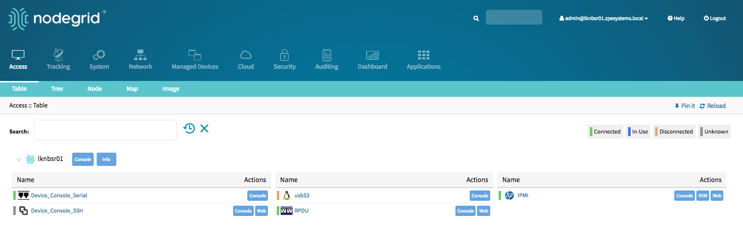
Device Access
The Access page provides an overview of all available target devices. It allows users to easily connect to managed devices as well as review their current device status and search for target devices. The displayed target devices will be determent by the user's permissions as well as by the current state of Nodegrid Cloud nodes.
Device Sessions
The first view which is available to a user after login into the Web UI is the Access View. This view provides an overview of all available targets to which the user has access to. Each target will indicate its current connection status as well as the available connection types.
Connection Status is:
| State | Indicator Colour | Icon | Description |
|---|---|---|---|
| Connected | Green |  | Nodegrid can successfully connect to the target device and it is available for sessions |
| In-Use | Blue |  | The Device is currently in use |
| Disconnected | Orange |  | Nodegrid could not successfully connect to the target device and it is not available for sessions |
| Unknown | Grey |  | The connection status is unknown. This is the default state for target devices with the connection mode On-Demand or for new target devices for which the discovery process is not completed. |
Device sessions can be directly be started from this location.
Device Sessions - Web UI
A user has multiple options to start a device session from the WebUI. In the Access screen the user will directly see the available target sessions and can start a new session by just clicking on the connection button.
This will start a new window in which the target session will be established.
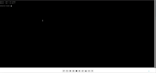
At the bottom of the window, the user is presented with buttons which allow the user to further control the target session and target device. The options available will depend on the connection type and device configuration.
| Options | Description |
|---|---|
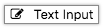 | The Text Input option allows a user to past larger text items directly into a session. |
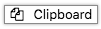 | The Clipboard options allows to for highlighted lines in the session to be copied out by a user |
 | The Info option will display the current device details |
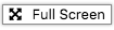 | The Fullscreen will expand the window to use the full screen. The session window itself will not expand beyond its maximum size change size |
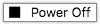 | The Power Off option will perform a power off on the target devices through a connected Rack PDU or IPMI device |
 | The Power On option will perform a power on on the target devices through a connected Rack PDU or IPMI device |
 | The Reset option will perform a power cycle on the target devices through a connected Rack PDU or IPMI device |
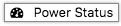 | The Power Status will display the current power status of a device as returned by a connected Rack PDU or IPMI device |
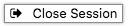 | This option closes the currently active session |
 | The plus sign expands or minimizes the command line options at the bottom of the screen |
By closing the window with the session to the target device will be closed.
Device Sessions - CLI
The access view is available in the CLI through the access menu, a user can directly navigate to this menu with cd /access. To see the currently available targets the user can use the command show.
Example:
xxxxxxxxxx[admin@nodegrid access]# showname status===================== =========Device_Console_SSH ConnectedDevice_Console_Serial InUseIPMI ConnectedRPDU ConnectedusbS2 Connected
A device session can be directly started from here with the connect command.
Use:
connect <target name>
Example:
x[admin@nodegrid access]# connect Device_Console_Serial[Enter '^Ec?' for help][Enter '^Ec.' to cli ]login:
Note: Only console sessions or sessions which provide a text-based interface can be started from the CLI.
After a connection is established the user use the Escape sequence ^Ec or ^O to further control the session.
Note: the Escape sequences can be changed in the device settings.
The following options are available.
| Option | Escape Sequence | Description |
|---|---|---|
| . | ^Ec. | disconnect the current session |
| g | ^Ecg | displays the current user group information |
| l | ^Ecl | sends the break signal as defined in the device settings |
| w | ^Ecw | displays the currently connected users |
| <cr> | ^Ec<cr> | sends a ignore/abort command signal |
| k | ^Eck | serial port(speed data bits parity stop bits flow) |
| b | ^Ecb | sends a broadcast message, a message can be typed after the escape sequence sent. |
| i | ^Eci | displays the current serial port information |
| s | ^Ecs | changes the current session to read-only mode |
| a | ^Eca | changes the current session to read-write mode |
| f | ^Ecf | forces the current session to read-write mode |
| z | ^Ecz | disconnect a specific connected user session |
| ? | ^Ec? | print this message |
Power Control options are available on targets which are connected to a managed Rack PDU or provide power control through IMPI. The power menu can be started with ^O
xxxxxxxxxxPower Menu - Device_Console_SerialOptions:1. Exit2. Status3. On4. Off5. CycleEnter option:
Device Information
Each device maintained by the Nodegrid platform has a multitude of device information stored in the system. This information is visible to users and fully searchable in the system. This is specifically useful when users are trying to identify specific targets.
The stored information is a combination of automatically discovered values, values which have been set during the device configuration and additional information which have been associated with a device by an administrator.
The device information can be displayed in the Access view for a specific device, by clicking on a target name in the Web UI or by navigating to the device in the CLI.
Display Device Information - Web UI
- Navigate to
Access:: Table - Click on the Target Name to display Device Details
Display Device Information - CLI
- Navigate to
cd /access/ - use the
showcommand to display the device details
xxxxxxxxxx[admin@nodegrid /]# cd /access/[admin@nodegrid access]# show Device_Console_Serial/name: Device_Console_Serialstatus: Connected
Device Views
The WebUI offers multiple ways to view and access target devices. By default, all users have displayed the Table view, which provides easy access to all targets. Other views are available and improve the accessibility or visualization of the current device status easier. The following views are available:
- Tabel View
- Tree View
- Node View
- Map View
- Image View
Each user can change the default view which will be displayed after login. For this, the user opens the preferred view and uses the Pin It button.

Note: The Table view is the only view which is available on the CLI.
Table View
The table view allows for easy access to all target device and their device sessions. It provides a table view which outlines easily the current status for each device. The view will display all devices currently connected to the unit as well as all other targets which are available through the Cloud feature.
The view supports filtering the current list by current device status and other search criteria. In order to filter by current device status Click on the device status icons in the top right-hand corner. The following example filters the devices by Connection State (Connected and In-Use)
More advanced search options are available through the Search field. See Device Search for more details.
Tree View
The Tree view displays all targets based on the physical hierarchies of the Nodegrid setup and allows to start connections for each target. It allows for easy access to targets devices based on their location, like Nodegrid name, city name, data center name, row and rack, and others. The View section offers filters, based on location and device types.
More advanced search options are available through the Search field. See Device Search for more details.
Node View
The Node View arranges all target devices around their connected Nodegrid units and makes it easy to get a complete overview of all targets and Nodegrid units in a Cloud. The View allows access to target device information and connections by clicking on the target nodes.
More advanced search options are available through the Search field. See Device Search for more details.
Map View
The Map View allows you to see the current status of your devices on a global map to get a complete overview of all targets and Nodegrid units in a Cloud. The Map View allows displaying precise location details down to a building level. The View allows accessing target device information and connections by clicking on the target nodes.
Global View
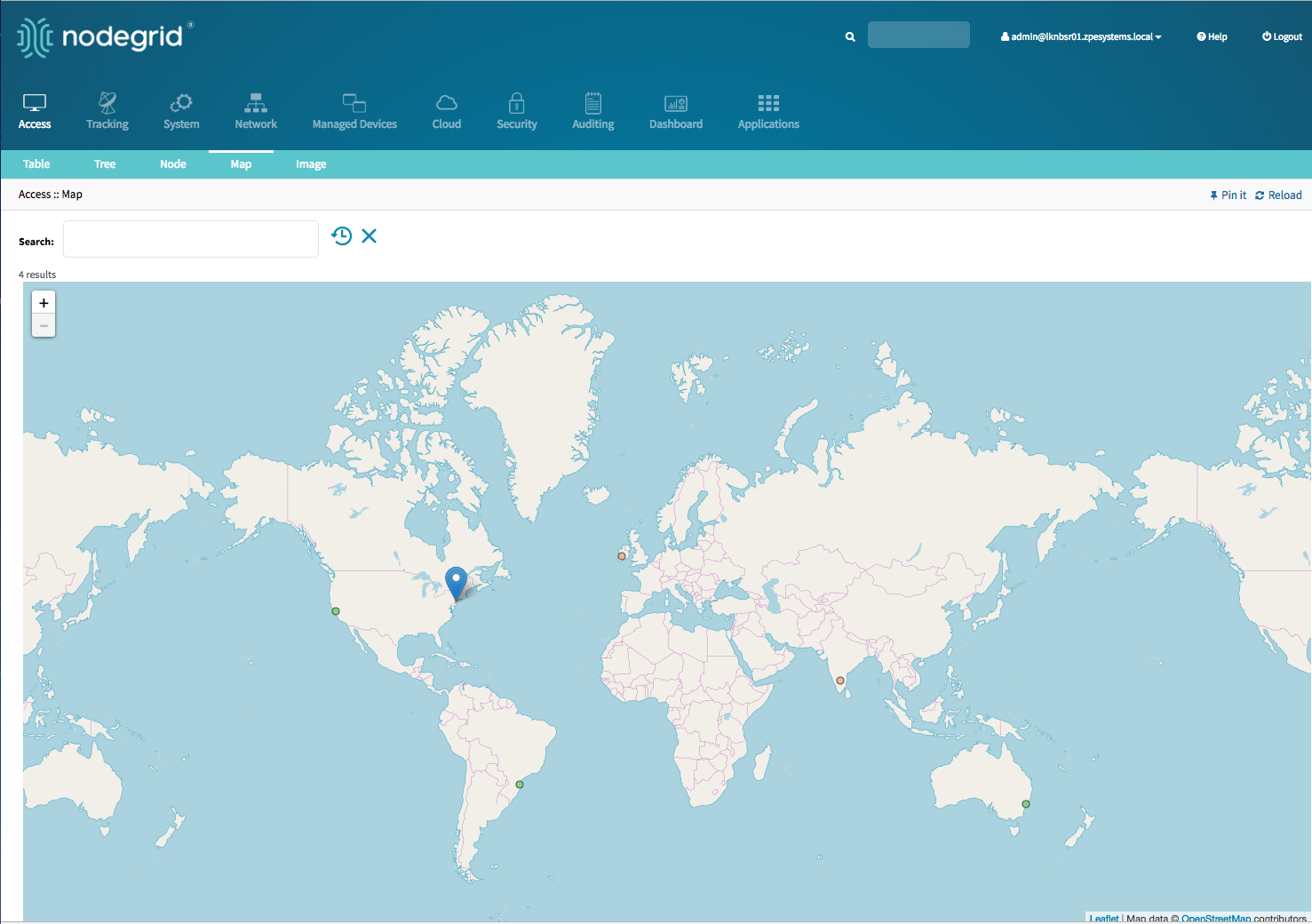
Street View
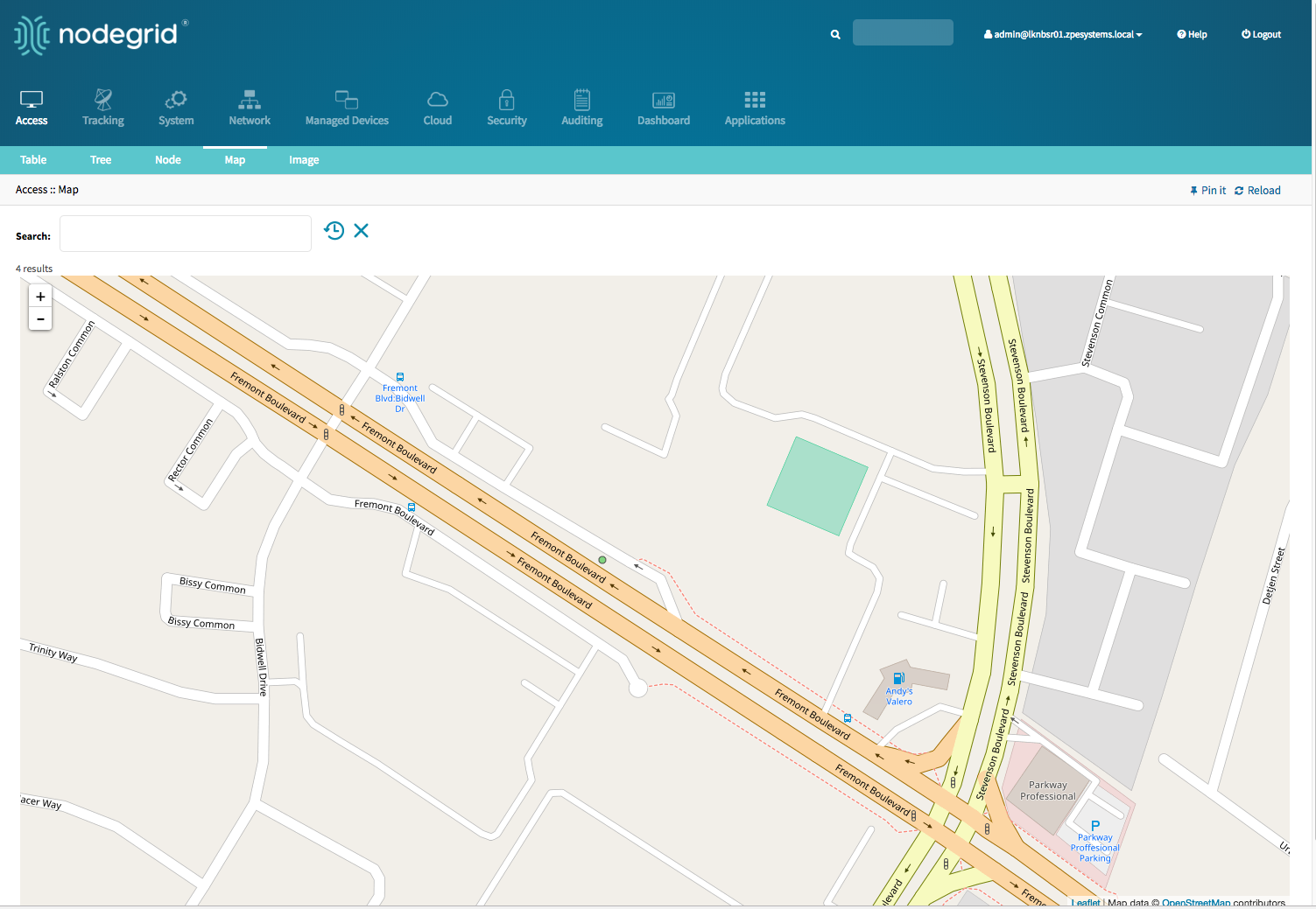
More advanced search options are available through the Search field. See Device Search for more details.
Image View
The Image View allows customers to display a custom view of there Nodegrid units and target devices and associated information. The implementation requires Professional Services implementation. Contact Customer Support support@zpesystem.com for additional information.
Search
The Nodegrid Platform provides advanced search capabilities which allow users to easily search and access the information and target devices they require.
Device Search
The Device Search is available on all Device views and provides an easy method to search and filter the Target devices in each view.
The Device Search can be accessed in the WebUI through the search field in the top left-hand corner of each view and on the CLI with the search command in the access menu. The NodeIQ™ Natural Language Search allows users to search for device property fields, including custom fields. This function works naturally with stand-alone units as well across all Nodegrid units in a Cloud configuration. The System automatically updates all the information about device changes and newly added devices and their properties in the background.
The Search filed supports the following keywords:
| Keyword | Description |
|---|---|
| [Search String] | a search string which represents part of or a compleat string to be searched for |
| AND | Combines multiple search strings with an AND |
| OR | Combines multiple search strings with an OR. Default search behaviour for more than one search string |
| NOT | Any targets matching the search string will NOT be returned |
| [Field Name] | Allows limit of the Search String to a specific Field Name |
Note: The keywords AND, OR and NOT are case sensitive. and, or, not will be identified as search strings.
To search for standard and custom field data (including groups, such as “admin” group), IP addresses or a specific device, follow the examples below:
Example with AND
“PDU AND IPMI”
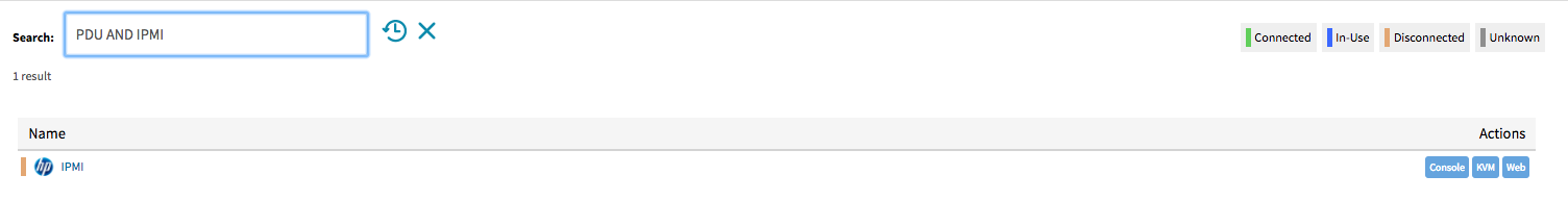
xxxxxxxxxx[admin@nodegrid search]# search "PDU AND IPMI"search: PDU AND IPMIresults: 1 resultpage: 1 of 1[admin@nodegrid search]# showname status action==== ====== ======IPMI -
Example with OR
"PDU OR IPMI"
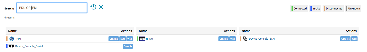
xxxxxxxxxx[admin@nodegrid access]# search "PDU OR IPMI"search: PDU OR IPMIresults: 4 resultspage: 1 of 1[admin@nodegrid search]# showname status action===================== ====== ======IPMI -RPDU -Device_Console_SSH -Device_Console_Serial -
"PDU IPMI"
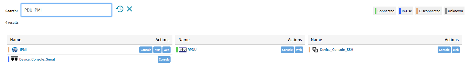
xxxxxxxxxx[admin@nodegrid access]# search "PDU IPMI"search: PDU IPMIresults: 4 resultspage: 1 of 1[admin@nodegrid search]# showname status action===================== ====== ======IPMI -RPDU -Device_Console_SSH -Device_Console_Serial -
Example with NOT
"PDU AND NOT IPMI"
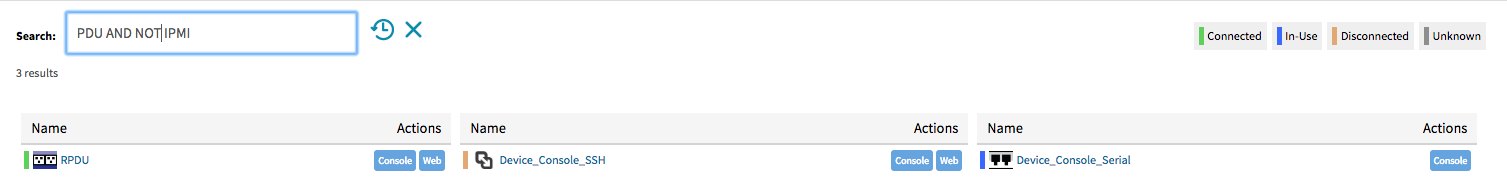
xxxxxxxxxx[admin@nodegrid search]# search "PDU AND NOT IPMI"search: PDU AND NOT IPMIresults: 3 resultspage: 1 of 1[admin@nodegrid search]# showname status action===================== ====== ======RPDU -Device_Console_SSH -Device_Console_Serial -
Example with Field Name
"name:PDU"
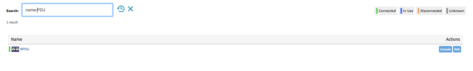
xxxxxxxxxx[admin@nodegrid search]# search "name:PDU"search: name:PDUresults: 1 resultpage: 1 of 1[admin@nodegrid search]# showname status action==== ====== ======RPDU -
Global Search
A Global Search option is available in the WebUI. The Search field is located at the top of the screen beside the current user information and logs out option. The global search works in the same way as the Device Search and supports the same keywords. The Search is available from all screens and allows easy access to all target devices and target sessions.
Device Management (Managed Devices)
The Managed Devices Section allows users to configure, create and delete target devices. The Nodegrid Platform supports target devices which are connected through a serial, USB, or network connection. The following protocols are currently supported for network-based devices Telnet, SSH, HTTP/S, IMPI variations and SNMP.
The user has multiple options to enable or create and new target devices. They can be manually enabled/created or can be discovered.
Each managed device added in the system uses one license from the pool. Each unit is shipped with enough perpertual licenses to cover the amount of physical ports and no further licenses are required to utilize the physical ports. Additional licenses can be added to a unit to allow it to manage additional devices. If licenses expire or are deleted from the system, the devices exceeding the total licenses will have their status changed to “unlicensed”. While their information will be retained in the system, the unlicensed devices will not show up in the access page preventing the user from connecting to them. Only licensed devices are listed on the access page and are available for access and management. The top right corner of the Managed Devices view shows the total licenses in the system, total in use and total available licenses. See Licenses for more details.
The Nodegrid platform supports the following managed device types.
Console connections utilizing RS232 protocol. Supported on Nodegrid Consol Server and Nodegrid Services Router family.
Service Processor Devices utilising:
- IPMI 1.5
- IPMI 2.0
- Hewleat Peckard iLO
- Oracle/SUN iLOM
- IBM IMM
- Dell DRAC
- Dell iDRAC
Console Server connections utilizing ssh protocol
Console Server connections utilizing
- Vertiv ACS Classic family
- Vertiv ACS6000 family
- Lantronix Console Server family
- Opengear Console Server family
- Digi Console Server fimily
KVM (Keyboard, Video, Mouse) Switches utilizing
- Vertiv DSR family
- Vertiv MPU family
- Atem Enterprise KVM family
- Raritan KVM family
- ZPE Systems KVM module
Rack PDUs from
- APC
- Baytech
- Eaton
- Enconnex
- Vertiv (PM3000 and MPH2)
- Raritan
- Servertech
Cisco UCS
Netapp
Infrabox
Virtual Machine sessions from
- VMWare
- KVM
Sensors
- ZPE Systems Temperature and Humidity Sensor
Configuration of Managed Devices
New devices can be added to the Devices menu. The menu offers the options to:
enable,disable,configureandresetdevices connected to physical portsadd,deleteandconfiguredevices connected through a network connectionrenameexisting devices/portscloneexisting devices- to quickly change the connection mode to
On-Demand - To
Bounce DTRsignal for serial ports
To perform any of these tasks either click on the button or select first a device and then click the button in the WebUI or use the command in the CLI.
WebUI Enable Port 1 example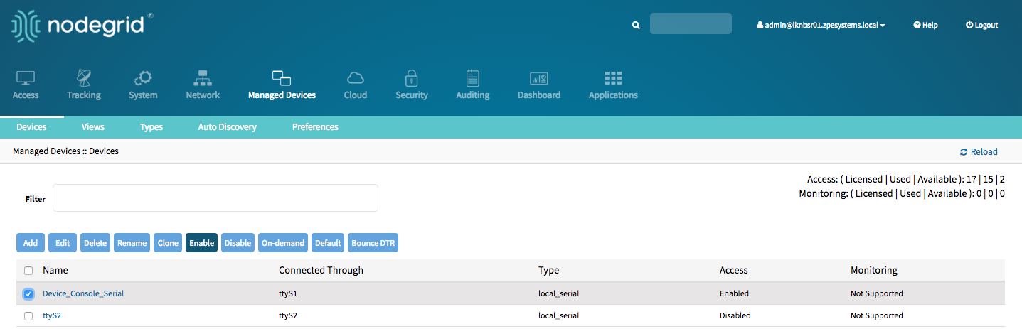
CLI rename port 2 example
xxxxxxxxxx[admin@nodegrid devices]# rename ttyS2[admin@nodegrid {devices}]# set new_name=Port2[admin@nodegrid {devices}]# commit
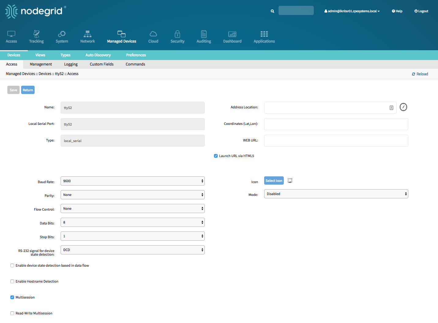
Serial Devices
The Nodegrid Platform supports RS-232 Serial connections thought the available Serial and USB interfaces. The ports are automatically detected and displayed in the Devices menu and can directly be used. Each port needs to be enabled and configured to provide access to the target device.
Before configuring the Nodegrid port check the console port settings of the target device with the manufacturer. Most devices use settings of 9600,8,N,1,N which is the default for the port
The Nodegrid Console Server S Series support advanced auto-detection which simplify the configuration process, by automatically detecting the cable pinout (Legacy and Cisco) and connection speed.
Configure Serial Devices - WebUI
Navigate to
Managed Devices:: DevicesClick on the port or select the port and click on
Edit. Multiple Ports can be selectedConfirm the values for:
Baud Rateset it to the correct speed matching the target device settings or toAutoParitypossible values are: None (default), Odd, or EvenFlow Controlpossible values are: None (default), Software, HardwareData Bitspossible values are: 5,6,7,8 (default)Stop Bitspossible values are: 1RS-232 signal for device state detectionpossible values are: DCD (default), None, CTSModepossible values are: Enabled, On-Demand, Disabled
Optional, settings which control the display and behavior of the device can be adjusted at this time. See Device Settings for more details
Configure Serial Devices - CLI
Navigate to
/settings/devicesuse the
editcommand with the port name to change the port configuration. Multiple ports can be defineduse the
showcommand to display the current valuesuse the
setcommand adjust the values for:baud_rateset it to the correct speed matching the target device settings or toAutoparitypossiable values are: None (default), Odd, or Evenflow_controlpossiable values are: None (defualt), Software, Hardwaredata_bitspossiable values are: 5,6,7,8 (default)stop_bitspossiable values are: 1rs-232_signal_for_device_state_detectionpossiable values are: DCD (default), None, CTSmodepossiable values are: Enabled, On-Demand, Disabled
Optional, settings which controll the display and behavior of the device can be adjusted at this time. See Device Settings for more details
use the
commitcommand to chang the settings
xxxxxxxxxx[admin@nodegrid /]# cd /settings/devices[admin@nodegrid devices]# edit ttyS2[admin@nodegrid {devices}]# showname: ttyS2type: local_serialaddress_location =coordinates =web_url =launch_url_via_html5 = yesbaud_rate = 9600parity = Noneflow_control = Nonedata_bits = 8stop_bits = 1rs-232_signal_for_device_state_detection = DCDenable_device_state_detection_based_in_data_flow = noenable_hostname_detection = nomultisession = yesread-write_multisession = noicon = terminal.pngmode = disabledskip_authentication_to_access_device = noescape_sequence = ^Ecpower_control_key = ^Oshow_text_information = yesenable_ip_alias = noenable_second_ip_alias = noallow_ssh_protocol = yesssh_port =allow_telnet_protocol = yestelnet_port = 7002allow_binary_socket = nodata_logging = no[admin@nodegrid {devices}]# set mode=enabled baud_rate=Auto[admin@nodegrid {devices}]# commit
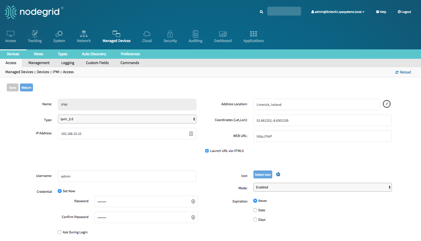
Service Processor Devices
The Nodegrid platform supports multiple IPMI based Service Processors like IPMI 1.5, IMPI 2.0, Hewlett Packard ILO's, Oracle/SUN iLOM's, IBM IMM's, Dell DRAC and iDRAC.
In order to manage these devices, the Nodegrid requires a valid network connection to the target device. This can be through a dedicated network interface on the Nodegrid itself or through an existing network connection.
The Nodegrid supports the following features for Service Processors.
Note: Some features might not be available depending on the Service Processor capabilities.
- Serial Over LAN (SOL)
- Web Interface
- KVM sessions
- support for Virtual Media
- Power Control
- Data Logging
- Event Logging
- Power Control through Rack PDU
For console access via SOL, you must also enable BIOS console redirect and OS console redirect (typically for Linux OS) on the server.
Add Service Processor Devices - WebUI
- Navigate
Managed Devices:: Devices, - click the
Addbutton to add a device to the system. For the purpose of this example, provide the following information: - Enter the name of the server you want to add.
- Enter the IP address of the service processor. Make sure the IP address is reachable by the Nodegrid platform.
- In the
Typefield, select a type that matches the service processor in use. Possible values are: ipmi1.5,ipmi2.0, ilo, ilom, imm, drac, idrac6 - Enter
usernameandpasswordof the service processor, or selectAsk During Loginoption if you want to provide user credentials during the login time - click the Save button.
- Optional, settings which control the display and behaviour of the device can be adjusted at this time. See Device Settings for more details.
Add Service Processor Devices - CLI
Navigate to
/settings/devicesuse the
addcommand to create a new deviceuse the
setcommand to define the following settingsnametype, possible values are: ipmi1.5,ipmi2.0, ilo, ilom, imm, drac, idrac6ip_addressusernameandpasswordof the service processor, or selectAsk During Loginoption if you want to provide user credentials during the login time
save the changes with
commitOptional, settings which control the display and behaviour of the device can be adjusted at this time. See Device Settings for more details.
[admin@nodegrid /]# cd /settings/devices
[admin@nodegrid devices]# add
[admin@nodegrid {devices}]# set name=IPMI
[admin@nodegrid {devices}]# set type=ipmi_2.0
[admin@nodegrid {devices}]# set ip_address=192.168.10.11
[admin@nodegrid {devices}]# set credential=ask_during_login

or

[admin@nodegrid {devices}]# set credential=set_now
[admin@nodegrid {devices}]# set username=admin password=admin

[admin@nodegrid {devices}]# commit
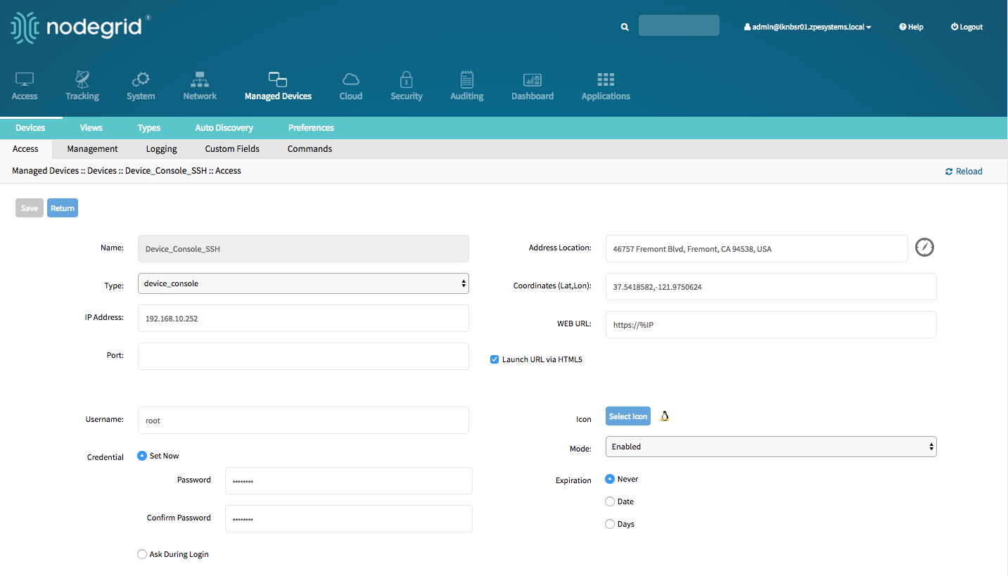
Devices with SSH
The Solution supports the management of target devices through SSH. The Nodegrid supports the following features for these devices:
- Console Session
- Data Logging
- Custom Commands
- Web Sessions
- Power Control through Rack PDU
Add Devices with SSH - WebUI
- Navigate
Managed Devices:: Devices, - click the
Addbutton to add a device to the system. - Enter the name of the server you want to add.
- Enter the IP address of the device. Make sure the IP address is reachable by the Nodegrid platform.
- In the
Typefield, select a type that matches the ssh or telnet in use. Possible values are: device_console - Enter
usernameandpasswordof the ssh server, or selectAsk During Loginoption if you want to provide user credentials during the login time - click the Save button.
- Optional, settings which control the display and behavior of the device can be adjusted at this time. See Device Settings for more details.
Add Devices with SSH - CLI
Navigate to
/settings/devicesuse the
addcommand to create a new deviceuse the
setcommand to define the following settingsnametype, possible values are: device_consoleip_addressusernameandpasswordof the device, or selectAsk During Loginoption if you want to provide user credentials during the login time
save the changes with
commitOptional, settings which control the display and behavior of the device can be adjusted at this time. See Device Settings for more details.
[admin@nodegrid /]# cd /settings/devices
[admin@nodegrid devices]# add
[admin@nodegrid {devices}]# set name=Device_Console_SSH
[admin@nodegrid {devices}]# set type=device_console
[admin@nodegrid {devices}]# set ip_address=192.168.10.252
[admin@nodegrid {devices}]# set credential=ask_during_login

or

[admin@nodegrid {devices}]# set credential=set_now
[admin@nodegrid {devices}]# set username=admin password=admin

[admin@nodegrid {devices}]# commit
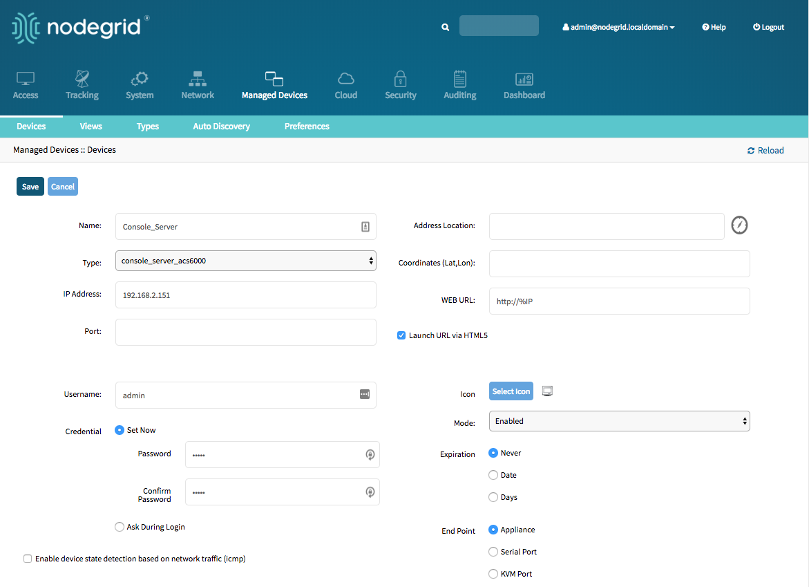
Console Servers
The Solution supports multiple 3rd party Console Servers from different vendors, including console servers from Avocent and Servertech. These devices can be added to the Nodegrid Platform and the system will then allow using the connected targets as if they would have been directly connected to a Nodegrid appliance. Adding 3rd party Console Servers is a two-step process, in the first step the 3rd party appliance is added to the Nodegrid and in a 2nd step, all enabled ports will be added to the platform.
The Nodegrid supports the following features for these devices:
- Console Session
- Data Logging
- Custom Commands
- Web Sessions
- Power Control through Rack PDU
Add Console Servers - WebUI
- Navigate
Managed Devices:: Devices, - click the
Addbutton to add a device to the system. - Enter the name of the console server you want to add.
- Enter the IP address of the console server. Make sure the IP address is reachable by the Nodegrid platform.
- In the
Typefield, select a type that matches the console server. Possible values are: console_server_acs, console_server_acs6000,console_server_lantronix,console_server_opengear,console_server_digicp_ - Enter
usernameandpasswordof the console server, or selectAsk During Loginoption if you want to provide user credentials during the login time - click the Save button.
- Optional, settings which control the display and behavior of the device can be adjusted at this time. See Device Settings for more details.
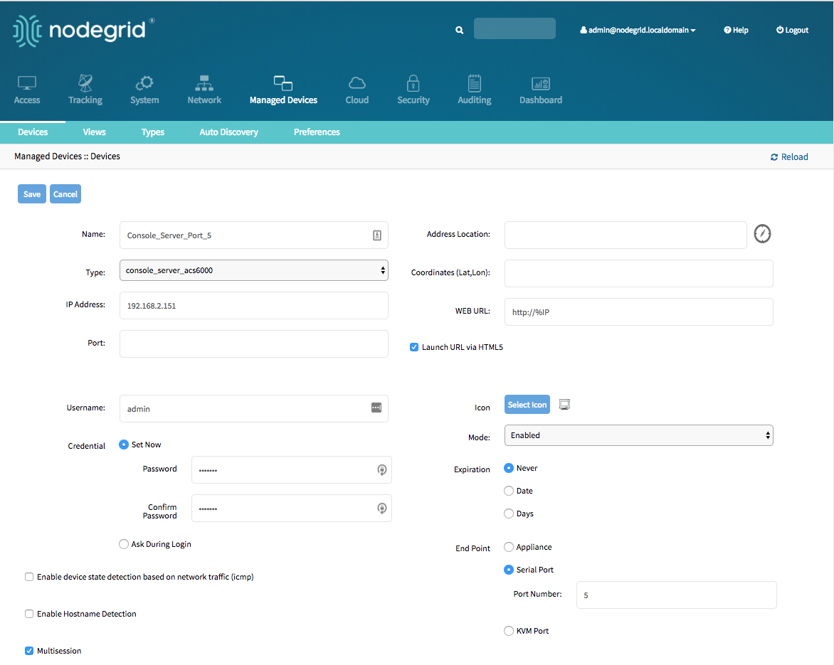
Add Console Server Ports - WebUI
- Navigate
Managed Devices:: Devices, - click the
Addbutton to add a device to the system. - Enter the name of the console server port you want to add.
- Enter the IP address of the console server. Make sure the IP address is reachable by the Nodegrid platform.
- In the
Typefield, select a type that matches the console server. Possible values are: console_server_acs, console_server_acs6000,console_server_lantronix,console_server_opengear,console_server_digicp_ - Enter
usernameandpasswordof the console server, or selectAsk During Loginoption if you want to provide user credentials during the login time - Select as
End PointSerial Port and enter the port number - click the Save button.
Note: Ports can be automatically detected and added see Auto Discovery Section for details
Add Console Servers - CLI
Navigate to
/settings/devicesuse the
addcommand to create a new deviceuse the
setcommand to define the following settingsnametype, possiable values are: console_server_acs, console_server_acs6000,console_server_lantronix,console_server_opengear,console_server_digicp_ip_addressusernameandpasswordof the device, or selectAsk During Loginoption if you want to provide user credentials during the login timeendpointshould be defined as appliance
save the changes with
commitOptional, settings which controll the display and behavior of the device can be adjusted at this time. See Device Settings for more details.
[admin@nodegrid /]# cd /settings/devices
[admin@nodegrid devices]# add
[admin@nodegrid {devices}]# set name=Console_Server
[admin@nodegrid {devices}]# set type=console_server_acs6000
[admin@nodegrid {devices}]# set ip_address=192.168.2.151
[admin@nodegrid {devices}]# set end_point = appliance
[admin@nodegrid {devices}]# set credential=ask_during_login

or

[admin@nodegrid {devices}]# set credential=set_now
[admin@nodegrid {devices}]# set username=admin password=admin

[admin@nodegrid {devices}]# commit
Add Console Server Ports - CLI
Navigate to
/settings/devicesuse the
addcommand to create a new deviceuse the
setcommand to define the following settingsnametype, possiable values are: console_server_acs, console_server_acs6000,console_server_lantronix,console_server_opengear,console_server_digicp_ip_addressusernameandpasswordof the device, or selectAsk During Loginoption if you want to provide user credentials during the login timeendpointshould be defined as serial_portport_numbershould be defined as the port number
save the changes with
commitOptional, settings which controll the display and behavior of the device can be adjusted at this time. See Device Settings for more details.
Note: Ports can be automatically detected and added see Auto Discovery Section for details
[admin@nodegrid /]# cd /settings/devices
[admin@nodegrid devices]# add
[admin@nodegrid {devices}]# set name=Console_Server_Port_5
[admin@nodegrid {devices}]# set type=console_server_acs6000
[admin@nodegrid {devices}]# set ip_address=192.168.2.151
[admin@nodegrid {devices}]# set end_point = serial_port
[admin@nodegrid {devices}]# set port_number = 5
[admin@nodegrid {devices}]# set credential=ask_during_login

or

[admin@nodegrid {devices}]# set credential=set_now
[admin@nodegrid {devices}]# set username=admin password=admin

[admin@nodegrid {devices}]# commit
KVM Switches
The Solution supports multiple 3rd party KVM Switches from different vendors, including products from Avocent and Raritan. These devices can be added to the Nodegrid Platform and the system will then allow using the connected targets as if they would have been directly connected to a Nodegrid appliance. Adding 3rd party KVM Switches is a two-step process, in the first step the 3rd party appliance is added to the Nodegrid and in a 2nd step, all enabled ports will be added to the platform.
The Nodegrid supports the following features for these devices:
- KVM Session
- Web Sessions
- Power Control through Rack PDU
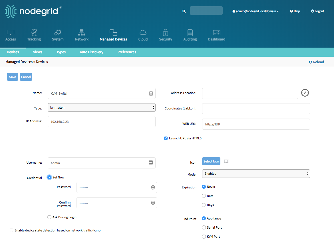
Add KVM Switches - WebUI
- Navigate
Managed Devices:: Devices, - click the
Addbutton to add a device to the system. - Enter the name of the KVM switch you want to add.
- Enter the IP address of the KVM switch. Make sure the IP address is reachable by the Nodegrid platform.
- In the
Typefield, select a type that matches the KVM switch. Possible values are: kvm_dsr, kvm_mpu,kvm_aten,kvm_raritan - Enter
usernameandpasswordof the KVM switch, or selectAsk During Loginoption if you want to provide user credentials during the login time - click the Save button.
- Optional, settings which control the display and behavior of the device can be adjusted at this time. See Device Settings for more details.
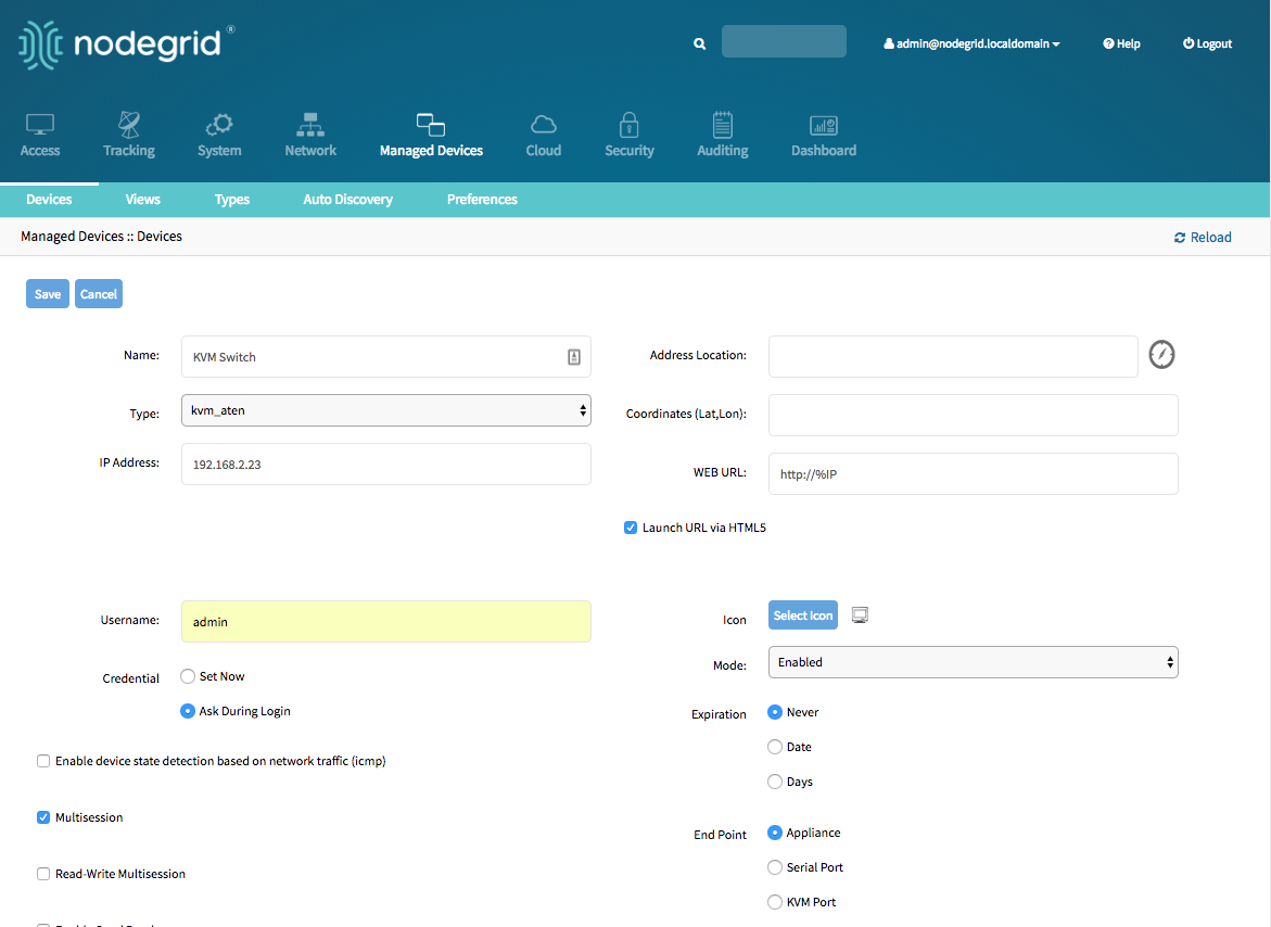
Add KVM Switch Ports - WebUI
- Navigate
Managed Devices:: Devices, - click the
Addbutton to add a device to the system. - Enter the name of the KVM switch port you want to add.
- Enter the IP address of the KVM switch. Make sure the IP address is reachable by the Nodegrid platform.
- In the
Typefield, select a type that matches the KVM switch. Possible values are: kvm_dsr, kvm_mpu,kvm_aten,kvm_raritan - Enter
usernameandpasswordof the KVM switch, or selectAsk During Loginoption if you want to provide user credentials during the login time - Select as
End PointKVM Port and enter the port number - click the Save button.
Note: Ports can be automatically detected and added see Auto Discovery Section for details
Add KVM Switches - CLI
Navigate to
/settings/devicesuse the
addcommand to create a new deviceuse the
setcommand to define the following settingsnametype, possible values are: kvm_dsr, kvm_mpu,kvm_aten,kvm_raritanip_addressusernameandpasswordof the device, or selectAsk During Loginoption if you want to provide user credentials during the login timeendpointshould be defined as appliance
save the changes with
commitOptional, settings which control the display and behavior of the device can be adjusted at this time. See Device Settings for more details.
[admin@nodegrid /]# cd /settings/devices
[admin@nodegrid devices]# add
[admin@nodegrid {devices}]# set name=KVM_Switch
[admin@nodegrid {devices}]# set type=kvm_aten
[admin@nodegrid {devices}]# set ip_address=192.168.2.151
[admin@nodegrid {devices}]# set end_point = appliance
[admin@nodegrid {devices}]# set credential=ask_during_login

or

[admin@nodegrid {devices}]# set credential=set_now
[admin@nodegrid {devices}]# set username=admin password=admin

[admin@nodegrid {devices}]# commit
Add KVM Switch Ports - CLI
Navigate to
/settings/devicesuse the
addcommand to create a new deviceuse the
setcommand to define the following settingsnametype, possible values are: kvm_dsr, kvm_mpu,kvm_aten,kvm_raritanip_addressusernameandpasswordof the device, or selectAsk During Loginoption if you want to provide user credentials during the login timeendpointshould be defined as serial_portport_numbershould be defined as the port number
save the changes with
commitOptional, settings which control the display and behavior of the device can be adjusted at this time. See Device Settings for more details.
Note: Ports can be automatically detected and added see Auto Discovery Section for details
[admin@nodegrid /]# cd /settings/devices
[admin@nodegrid devices]# add
[admin@nodegrid {devices}]# set name=Console_Server_Port_5
[admin@nodegrid {devices}]# set type=kvm_aten
[admin@nodegrid {devices}]# set ip_address=192.168.2.151
[admin@nodegrid {devices}]# set end_point = kvm_port
[admin@nodegrid {devices}]# set port_number = 1
[admin@nodegrid {devices}]# set credential=ask_during_login

or

[admin@nodegrid {devices}]# set credential=set_now
[admin@nodegrid {devices}]# set username=admin password=admin

[admin@nodegrid {devices}]# commit
Rack PDU's
The Solution supports multiple 3rd party Rack PDUs from different vendors, including products from Avocent, Raritan, and Servertech. These devices can be added to the Nodegrid Platform and the system will then allow users to connect to the Rack PDU and control the power outlets should this function be supported by the Rack PDU. Outlets can then be associated to specific target devices, which allows users to directly control the specific power outlets for this target device.
The Nodegrid supports the following features for these devices:
- Console Sessions
- Data Logging
- Custom Commands
- Web Sessions
- Power Control of outlets
Note: The Power Control feature needs to be supported by the Rack PDU. Check the manual of the Rack PDU if the feature is available on a specific model.
Rack PDUs - WebUI
- Navigate
Managed Devices:: Devices - click the
Addbutton to add a device to the system. - Enter the name of the Rack PDU you want to add.
- Enter the IP address of the Rack PDU. Make sure the IP address is reachable by the Nodegrid platform.
- In the
Typefield, select a type that matches the Rack PDU. Possible values are: pdu_apc, pdu_baytech,pdu_eaton,pdu_mph2,pdu_pm3000,pdu_raritan,pdu_servertech,pdu_enconnex - Enter
usernameandpasswordof the Rack PDU, or selectAsk During Loginoption if you want to provide user credentials during the login time - click the Save button.
- Optional, settings which control the display and behavior of the device can be adjusted at this time. See Device Settings for more details.
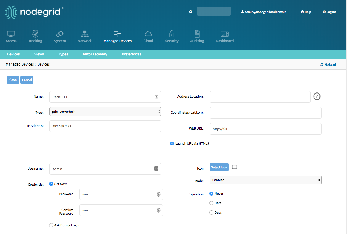
Note: By default will Nodegrid communicate with the Rack PDU using ssh/telnet. The reaction time of Rack PDUs using these interface is typically very slow. It is therefore recommended to use SNMP for the communication with the Rack PDU if possible.
- Navigate
Managed Devices:: Devices - Click on the
Nameof the newly added Rack PDU - Navigate to the
Commandsmenu and click on Outlets
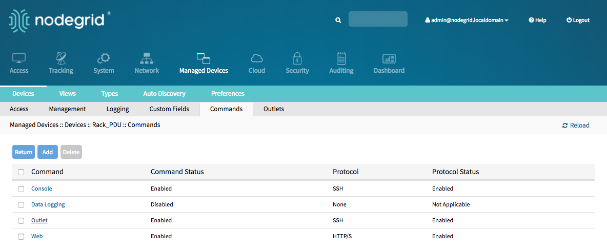
- Change the
Protocolto SNMP and click on Save
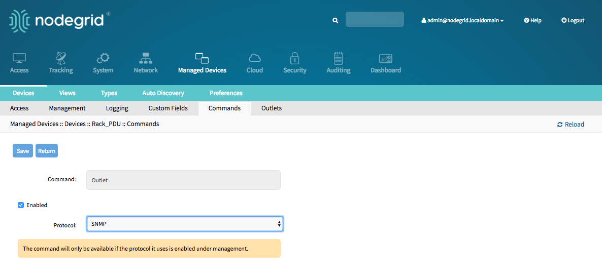
- Navigate to the
Managementmenu and update the SNMP values to match the settings on the Rack PDU, click onSave
Note: Use SNMP details which provide read and write access. With Read-Only credentials can the Nodegrid Platform not control the power outlets.
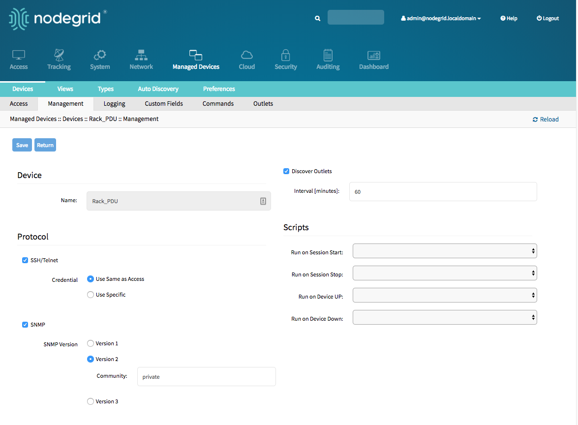
- The Rack PDU Outlets will be automatically discovered, this process can take a few minutes, depending on the Rack PDU.
Add Rack PDU - CLI
Navigate to
/settings/devicesuse the
addcommand to create a new deviceuse the
setcommand to define the following settingsnametype, possiable values are: pdu_apc, pdu_baytech,pdu_eaton,pdu_mph2,pdu_pm3000,pdu_raritan,pdu_servertech,pdu_enconnexip_addressusernameandpasswordof the device, or selectAsk During Loginoption if you want to provide user credentials during the login timeendpointshould be defined as appliance
save the changes with
commitOptional, settings which controll the display and behavior of the device can be adjusted at this time. See Device Settings for more details.
Note: By default will Nodegrid communicate with the Rack PDU using ssh/telnet. The reaction time of Rack PDUs using these interface is typically very slow. It is therefore recommended to use SNMP for the communication with the Rack PDU if possible.
- Navigate to
/settings/devices/<device name>/commands/outlet - Change the protocol to SNMP
- Navigate to
/settings/devices/<device name>/managment - Enable SNMP and select the desired SNMP version and details
- Save the changes with
commit
Note: Use SNMP details which provide read and write access. With Read-Only credentials can the Nodegrid Platform not control the power outlets.
- The Rack PDU Outlets will be automatically discovered, this process can take a few minutes, depending on the Rack PDU.
[admin@nodegrid /]# cd /settings/devices
[admin@nodegrid devices]# add
[admin@nodegrid {devices}]# set name=Rack_PDU
[admin@nodegrid {devices}]# set type=pdu_servertech
[admin@nodegrid {devices}]# set ip_address=192.168.2.39
[admin@nodegrid {devices}]# set credential=ask_during_login

or

[admin@nodegrid {devices}]# set credential=set_now
[admin@nodegrid {devices}]# set username=admin password=admin

[admin@nodegrid {devices}]# commit
[admin@nodegrid /]# cd /settings/devices/Rack_PDU/commands/outlet
[admin@nodegrid outlet]# set protocol=snmp
[admin@nodegrid outlet]# cd /settings/devices/Rack_PDU/management/
[admin@nodegrid management]# set snmp=yes
[+admin@nodegrid management]# snmp_version = v2
[+admin@nodegrid management]# snmp_commmunity = private
[+admin@nodegrid management]# commit
Cisco UCS
The Solution supports the management of Cisco UCS through there Console Ports as well as there management interfaces. The Nodegrid supports the following features for these devices:
- Console Session
- Data Logging
- Event Logging
- Power Control through Cisco UCS appliance
- Web Session
- Custom Commands
Add Cisco UCS - WebUI
- Navigate
Managed Devices:: Devices, - click the
Addbutton to add a device to the system. - Enter the name of the Cisco UCS Blade to be added.
- Enter the IP address of the Blade Chassis. Make sure the IP address is reachable by the Nodegrid platform.
- In the
Typefield, select a type that matches the appliance. Possible values are: cimc_ucs - Enter the
Chassis IDand theBlade IDwhich represent the blade - Enter
usernameandpasswordof the Blade Chassis, or selectAsk During Loginoption if you want to provide user credentials during the login time - click the Save button.
- Optional, settings which control the display and behavior of the device can be adjusted at this time. See Device Settings for more details.
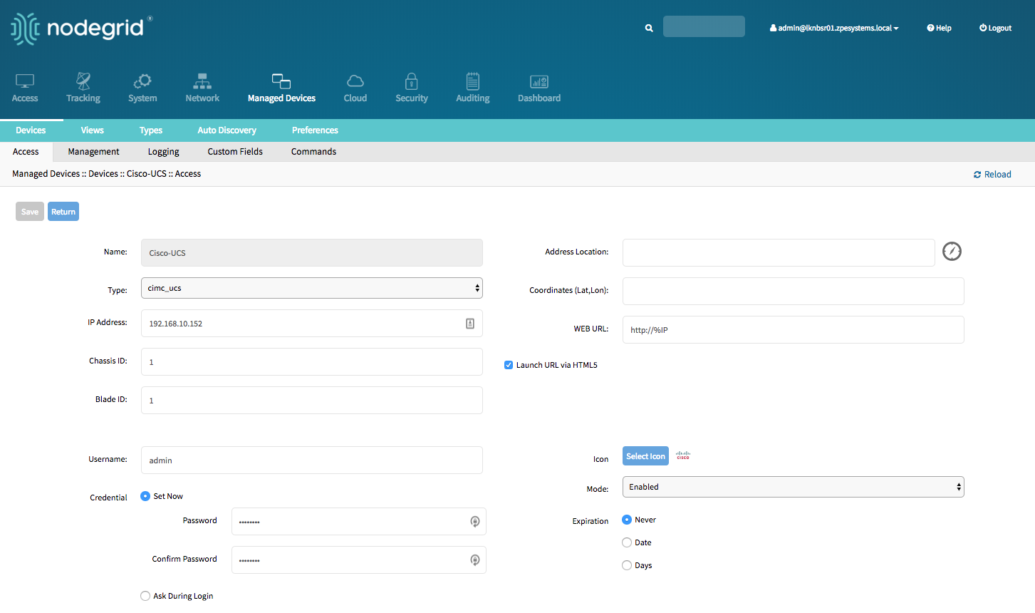
Add Cisco UCS - CLI
Navigate to
/settings/devicesuse the
addcommand to create a new deviceuse the
setcommand to define the following settingsnameof the blade to be addedtype, possible values are: cimc_ucsip_addressof the blade chassischassis_idof the blade chassisblade_idof the blade serverusernameandpasswordof the blade chassis, or selectAsk During Loginoption if you want to provide user credentials during the login time
save the changes with
commitOptional, settings which control the display and behaviour of the device can be adjusted at this time. See Device Settings for more details.
xxxxxxxxxx[admin@nodegrid /]# cd /settings/devices[admin@nodegrid devices]# add[admin@nodegrid {devices}]# set name=Cisco-UCS[admin@nodegrid {devices}]# set type=cimc_ucs[admin@nodegrid {devices}]# set ip_address=192.168.10.151[admin@nodegrid {devices}]# set chassis_id=1 blade_id=1s[admin@nodegrid {devices}]# set credential=ask_during_loginor[admin@nodegrid {devices}]# set credential=set_now[admin@nodegrid {devices}]# set username=admin password=admin[admin@nodegrid {devices}]# commit
Netapp
The Solution supports a management of Netapp appliances through there management interfaces. The Nodegrid supports the following features for these devices:
- Console Session
- Data Logging
- Event Logging
- Power Control through Netapp appliance
- Web Session
- Custom Commands
- Power Control through Rack PDU
Add Netapp - WebUI
- Navigate
Managed Devices:: Devices, - click the
Addbutton to add a device to the system. - Enter the name of the appliance you want to add.
- Enter the IP address of the device. Make sure the IP address is reachable by the Nodegrid platform.
- In the
Typefield, select a type that matches the NetApp appliance. Possible values are: netapp - Enter
usernameandpassword, or selectAsk During Loginoption if you want to provide user credentials during the login time - click the Save button.
- Optional, settings which control the display and behaviour of the device can be adjusted at this time. See Device Settings for more details.
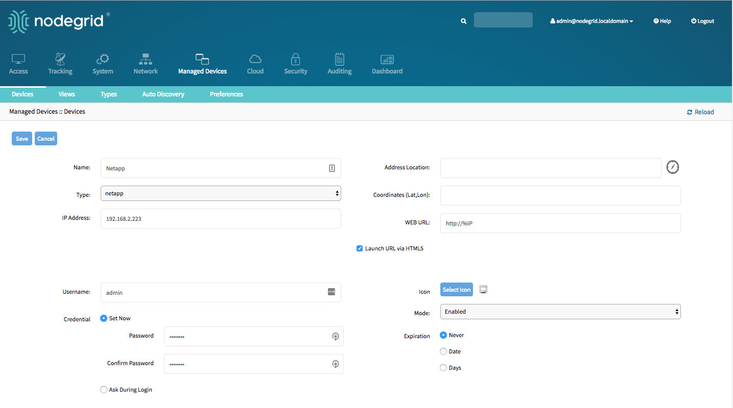
Add Netapp - CLI
Navigate to
/settings/devicesuse the
addcommand to create a new deviceuse the
setcommand to define the following settingsnametype, possible values are: netappip_addressusernameandpasswordof the device, or selectAsk During Loginoption if you want to provide user credentials during the login time
save the changes with
commitOptional, settings which control the display and behaviour of the device can be adjusted at this time. See Device Settings for more details.
[admin@nodegrid /]# cd /settings/devices
[admin@nodegrid devices]# add
[admin@nodegrid {devices}]# set name=Netapp
[admin@nodegrid {devices}]# set type=netapp
[admin@nodegrid {devices}]# set ip_address=192.168.10.250
[admin@nodegrid {devices}]# set credential=ask_during_login

or

[admin@nodegrid {devices}]# set credential=set_now
[admin@nodegrid {devices}]# set username=admin password=admin

[admin@nodegrid {devices}]# commit
Infrabox
The Solution supports the Smart Access Control for Rack's solution appliances (Infrabox) from InfraSolution. The Nodegrid supports the following features for these devices:
- Door Control
- Web Session
- Power Control through Rack PDU
Note: Communication to the appliances requires SNMP to be configured on the appliances
Add Infrabox - WebUI
- Navigate
Managed Devices:: Devices, - click the
Addbutton to add a device to the system. - Enter the name of the appliance you want to add.
- Enter the IP address of the device. Make sure the IP address is reachable by the Nodegrid platform.
- In the
Typefield, select a type that matches the Infrabox appliance. Possible values are: infrabox - Select
Ask During Loginand do not provide user credentials - click the Save button.
- Optional, settings which control the display and behaviour of the device can be adjusted at this time. See Device Settings for more details.
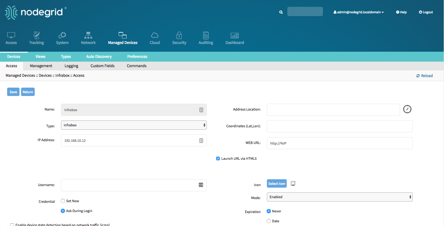
- Navigate to the
Managmentmenu and update the SNMP values to match the settings on the appliance - click on
Save
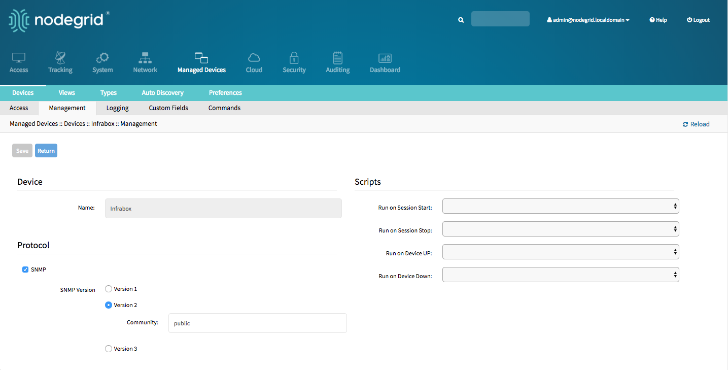
Add Infrabox - CLI
Navigate to
/settings/devicesuse the
addcommand to create a new deviceuse the
setcommand to define the following settingsnametype, possible values are: infraboxip_addressusernameandpasswordof the device, or selectAsk During Loginoption if you want to provide user credentials during the login time
save the changes with
commitOptional, settings which control the display and behaviour of the device can be adjusted at this time. See Device Settings for more details.
Navigate to
/settings/devices/<Device>/management/use the
setcommand to define the SNMP valuessnmp_versionsnmp_community
save the changes with
commit
[admin@nodegrid /]# cd /settings/devices
[admin@nodegrid devices]# add
[admin@nodegrid {devices}]# set name=Infrabox
[admin@nodegrid {devices}]# set type=infrabox
[admin@nodegrid {devices}]# set ip_address=192.168.10.250
[admin@nodegrid {devices}]# set credential=ask_during_login

or

[admin@nodegrid {devices}]# set credential=set_now
[admin@nodegrid {devices}]# set username=admin password=admin

[admin@nodegrid {devices}]# commit

[admin@nodegrid outlet]# cd /settings/devices/Infrabox/management/
[admin@nodegrid management]# set snmp=yes
[+admin@nodegrid management]# snmp_version=v2
[+admin@nodegrid management]# snmp_commmunity=private
[+admin@nodegrid management]# commit
Virtual Machines
The solution supports the management of VMWare virtual machines as well a KVM Virtual Machines. The Nodegrid supports the following features for these devices:
- MKS Sessions (for VMWare machines only)
- Virtual Serial console session (for VMWare machines only)
- Console session (for KVM machines only)
- Power Control through the hypervisor
- Web Session to the device
The system supports connection to ESX directly or VSphere servers. In case a connection is made directly the ESX server has to support the "vCenter agent for VMware Host" feature, which can be abled through a ESX server license. To check if the ESX server supports this feature, login to the ESX host and navigate to the License Feature section. Here are the available licenses and features listed which are supported by the host.
Note : In order to utilize the vSPC option with VMWare virtual machines the port needs to be configured on the Virtual Machine. See Appendix A: Configuring Virtual Serial Port (vSPC) on VM Servers
Add VMWare Virtual Machines - WebUI
Define a VM Manager
- Navigate to
Managed Devices :: Auto Discovery :: VM Managers - Click on
Addto define a new VM Manager - Provide the VCenter/ESXi IP or FQDN in
VM Serverfield - define the
UsernameandPasswordfor the server - adjust the
HTML console portif needed - Click on
Save
- Navigate to
Create a Device
- Navigate to
Managed Devices:: Devices - click the
Addbutton to add a device to the system. - Enter a name of the Virtual Mashine to be managed. The name has to match the name on the hypervisor
- Optional: enter the IP address of the Virtual Machine
- In the
Typefield, select a type that matches the Virtual Machine type. Possible values are: virtual_console_vmware - In
VM Managerfield select the correct hypervisor o which the machine runs - click the Save button.
- Navigate to
Add VMWare Virtual Machines - CLI
Define a VM Manager
Navigate to
/settings/auto_discovery/vm_managers/use the
addcommand to create a VM Manageruse the
setcommand to define the following settingsvm_server: Provide the VCenter/ESXi IP or FQDN- define
usernameandpassword - adjust the
html_console_portif needed
save the changes with
commit
[admin@nodegrid /]# cd /settings/auto_discovery/vm_managers/
[admin@nodegrid vm_managers]# add
[admin@nodegrid {vm_managers}]# set vm_server=VCenter
[admin@nodegrid {vm_managers}]# set username=admin
[admin@nodegrid {vm_managers}]# set password=password
[admin@nodegrid {vm_managers}]# commit
Create a Device
Navigate to
/settings/devicesuse the
addcommand to create a new deviceuse the
setcommand to define the following settingsnametype, possiable values are: virtual_console_vmware- optional,
ip_addressas of teh target device vm_manager, set to a existing VM Manager
save the changes with
commitOptional, settings which controll the display and behavior of the device can be adjusted at this time. See Device Settings for more details.
[admin@nodegrid /]# cd /settings/devices
[admin@nodegrid devices]# add
[admin@nodegrid {devices}]# set name=Virtual_Machine
[admin@nodegrid {devices}]# set type=virtual_console_vmware
[admin@nodegrid {devices}]# set ip_address=192.168.2.151
[admin@nodegrid {devices}]# set vm_manager=192.168.10.11
[admin@nodegrid {devices}]# commit
Add KVM Virtual Machines - WebUI
Create a Device
- Navigate to
Managed Devices:: Devices - click the
Addbutton to add a device to the system. - Enter a name of the Virtual Machine to be managed. The name has to match the name on the hypervisor
- enter the IP address of the KVM hypervisor
- provide the username and password for the KVM hypervisor
- In the
Typefield, select a type that matches the Virtual Machine type. Possible values are: virtual_console_kvm - click the Save button.
- Navigate to
Add KVM Virtual Machines - CLI
Create a Device
Navigate to
/settings/devicesuse the
addcommand to create a new deviceuse the
setcommand to define the following settingsnameor the virtual mashine, this has to match teh name of the machine on teh hypervisortype, possiable values are: virtual_console_kvmip_addressof the KVM hypervisor- provide
usernameandpasswordfor the KVM hypervisor
save the changes with
commitOptional, settings which controll the display and behavior of the device can be adjusted at this time. See Device Settings for more details.
[admin@nodegrid /]# cd /settings/devices
[admin@nodegrid devices]# add
[admin@nodegrid {devices}]# set name=virtual_machine_kvm
[admin@nodegrid {devices}]# set type=virtual_console_vmware
[admin@nodegrid {devices}]# set ip_address=192.168.10.11
[admin@nodegrid {devices}]# set username=root
[admin@nodegrid {devices}]# set password=password
[admin@nodegrid {devices}]# commit
Auto-Discovery
The Nodegrid Platform is able to automatically discover and add network devices, enabled ports on console servers, KVM switches and Virtual Serial Ports (VMWare) and Virtual Machines (VMWare).
This feature clones discovered devices from existing devices matching their profile and build dynamic access groups. For best results with this feature, make sure the device to be used as a reference in the cloning process is correctly configured. Verify that username, password and IP address are correct by accessing the device. Verify that the data logging and event logging settings are correct by auditing the log files. Verify that events are being detected based on data logging and event logging by simulating events and checking if any notification was created. Verify that the device is in the desirable authorization group with correct access rights.
The Auto Discovery follows the below general process:
- Create a template device, this device will be used to clone all the settings, with the exception of the connection details to the discovered devices. It is there for beneficial to configure all settings as they should appear on the end devices.
Note: For each target device type a template device needs to be created.
- For network devices create a
Network Scan - For virtual machines create a
Virtual Manager - for all devices create a
Discovery Rule, this step will link the template device with the discovery rules, which makes the decision which action will be taken with every discovered device - Start the discovery process. This step is automatic depending on the added device types. The Discovery Process is automatically started when an appliance is added to the platform and can manually be started at any point from
Managed Devices:: Auto Discovery:: Discover Nowin the WebUI or/settings/auto_discovery/discover_now/from CLI
Auto Discovery of Console Server and KVM Switch Ports
The Auto Discovery process can be used to automatically add and configure managed devices for 3rd party console server ports and KVM Switch ports. The process will discover all enabled ports on a managed appliance. The Console Server appliance and KVM Switches can be discovered using the Network Devices process see Auto Discovery of Network Devices.
Auto Discovery of Console Server and KVM Switch ports - WebUI
Create Template Device
- Navigate to
Managed Devices:: Devices - click the
Addbutton to add a device to the system. - Enter a name of the template you want to add
- Enter 127.0.0.1 for the IP address
- In the
Typefield, select a type that matches the console server. Possible values are: console_server_acs, console_server_acs6000,console_server_lantronix,console_server_opengear,console_server_digicp_ - Select
Ask During Login - Select as
End Pointas either Serial Port or KVM Port and enter the port number - Select as
ModeDisabled, this will ensure that the device is not displayed in the access page - click the Save button.
- Optional, settings which control the display and behaviour of the device can be adjusted at this time. See Device Settings for more details.
- Navigate to

Create Discovery Rule
- Navigate to
Managed Devices:: Auto Discovery:: Discovery Rules - click on
Addto add a new Discovery Rule - Enter a
Namefor the Discovery Rule - Select a
Statusfor the discovered rule, possible values are: Enabled, Disabled - As
Discovery Methodselect either Console Server Ports or KVM Ports - For
Port Listprovide a list of ports which should be scanned, examples are 1,3,5,10-20 - The
Host or VM Identifierparameter can be used to further apply a filter if a value is provided then part of the port name has to match the value - For
Actionselect an action which should be performed when a new device is discovered, possible values are: Clone (Mode:Enabled),Clone (Mode:On-Demand),Clone (Mode:Discovered),Discard discovered Devices - In the
Clone from fieldselect the template device which was created earlier - Click on
Saveto create the rule
- Navigate to
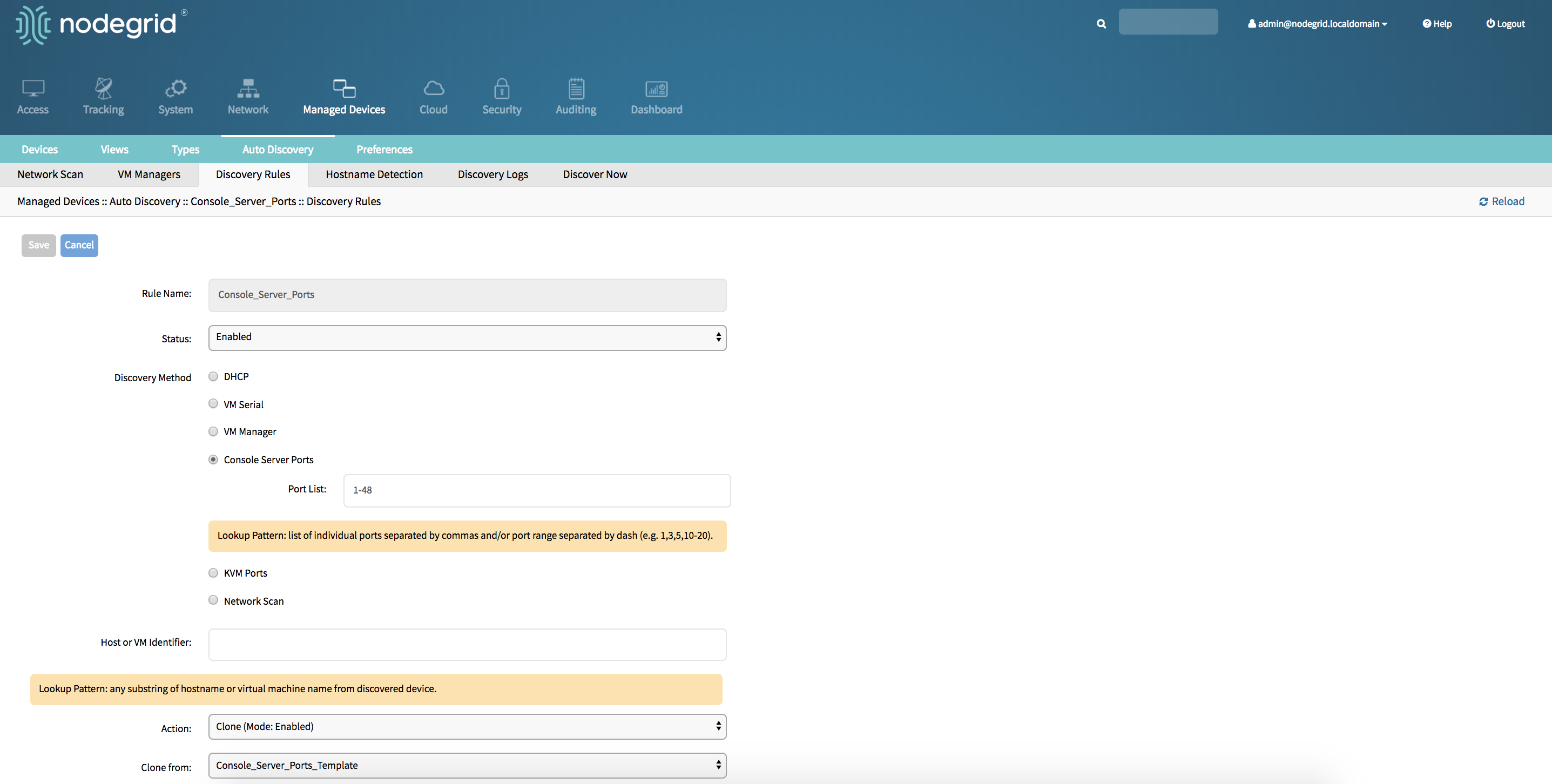
- Create a Console Server or KVM Switch appliance, see Add Console Servers for more details.
- After the appliance was created the Nodegrid Platform will automatically start discovering attached devices based on the created
Discovery Rules. This process will take a few minutes to complete.
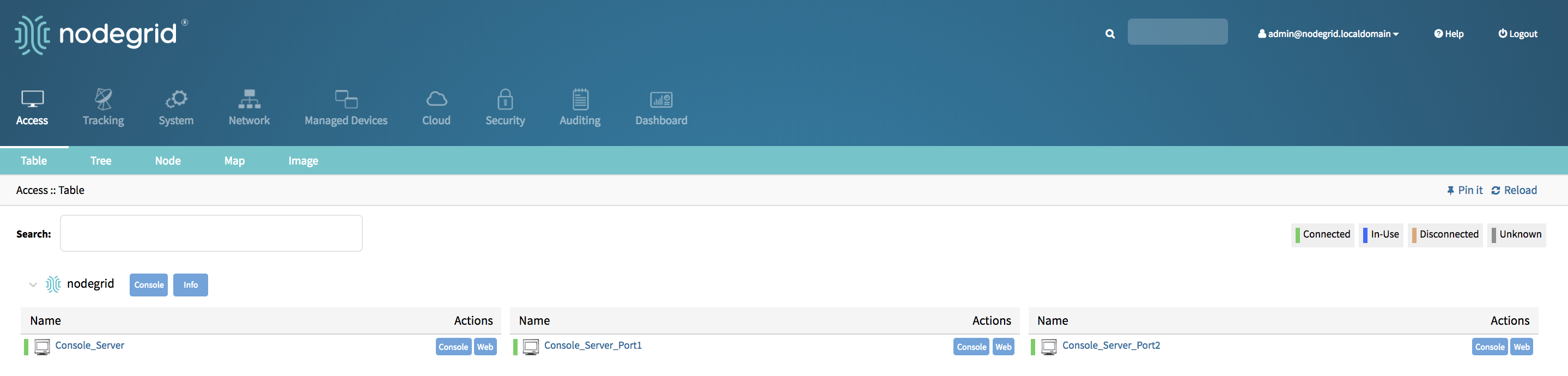
Auto Discovery of Console Server and KVM Switch ports - CLI
Create Template Device
Navigate to
/settings/devicesuse the
addcommand to create a new deviceuse the
setcommand to define the following settingsnametype, possiable values are: console_server_acs, console_server_acs6000,console_server_lantronix,console_server_opengear,console_server_digicp_ip_addressas 127.0.0.1- set user authentication to
Ask During Login endpointshould be defined as serial_port or kvm_portport_numbershould be defined as the port number- set
modeto disabled
save the changes with
commitOptional, settings which controll the display and behavior of the device can be adjusted at this time. See Device Settings for more details.
xxxxxxxxxx[admin@nodegrid /]# cd /settings/devices[admin@nodegrid devices]# add[admin@nodegrid {devices}]# set name=Console_Server_Port_Template[admin@nodegrid {devices}]# set type=console_server_acs6000[admin@nodegrid {devices}]# set ip_address=192.168.2.151[admin@nodegrid {devices}]# set end_point=serial_port[admin@nodegrid {devices}]# set port_number=1[admin@nodegrid {devices}]# set credential=ask_during_login[admin@nodegrid {devices}]# set mode=disabled[admin@nodegrid {devices}]# commit
Create Discovery Rule
Navigate to
/settings/auto_discovery/discovery_rules/use the
addcommand to create a Discovery Ruleuse the
setcommand to define the following settingsrule_namefor the Discovery Rulestatusfor the discovered rule, possiable values are: enabled, disabledmethodset to either console_server_ports or kvm_portsport_listprovide a list of ports which should be scanned, examples are 1,3,5,10-20host_identifierparameter can be used to further apply a filter, if a value is provided then part of the port name has to match the value
For
actionselect an action which should be performed when a new device is discovered, possiable values are: clone_mode_enabled,clone_mode_on-demand,clone_mode_discovered,discard_deviceclone_fromset to the template device which was created earliersave the changes with
commit
xxxxxxxxxx[admin@nodegrid /]# cd /settings/auto_discovery/discovery_rules/[admin@nodegrid discovery_rules]# add[admin@nodegrid {discovery_rules}]# set rule_name=Console_Server_Ports[admin@nodegrid {discovery_rules}]# set status=enabled[admin@nodegrid {discovery_rules}]# set method=console_server_ports[admin@nodegrid {discovery_rules}]# set port_list=1-48[admin@nodegrid {discovery_rules}]# set action=clone_mode_enabled[admin@nodegrid {discovery_rules}]# set clone_from=Console_Server_Ports_Template[admin@nodegrid {discovery_rules}]# commit
- Create a Console Server or KVM Switch appliance, see Add Console Servers for more details.
- After the appliance was created the Nodegrid Platform will automatically start discovering attached devices based on the created
Discovery Rules. This process will take a few minutes to complete.
Auto Discovery of Network Devices
Network appliances can be automatically discovered and added to the Nodegrid Platform. This includes appliances which support Telnet, SSH, ICMP, Console Servers, KVM Switches or IMPI protocols besides others. Appliances can be discovered through 3 separate method's, which can be combined or used independently:
- Similar Devices (select one of the devices from the drop-down menu),
- Port Scan and enter a list of ports in the Port List field,
- Ping
Auto Discovery of Network Devices - WebUI
Create Template Device
- Navigate to
Managed Devices:: Devices - click the
Addbutton to add a device to the system. - Enter a name of the template you want to add
- Enter 127.0.0.1 for the IP address
- In the
Typefield, select a type that matches the console server. Possible values are: device_console, ilo,imm,drac,idrac6,ipmi1.5,impi2.0,ilom,cimc_ucs,netapp,infrabox,pdu* - Enter
usernameandpassword, or selectAsk During Loginoption if you want to provide user credentials during the login time - Select as
ModeDisabled, this will ensure that the device is not displayed in the access page - click the Save button.
- Optional, settings which control the display and behaviour of the device can be adjusted at this time. See Device Settings for more details.
- Navigate to
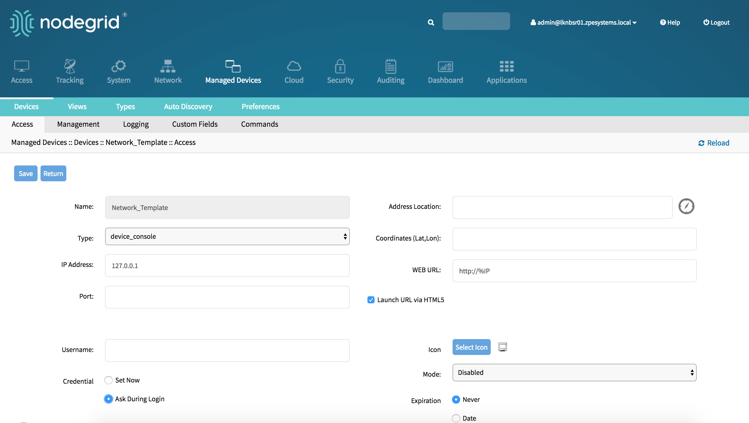
Create a Network Scan
Navigate to
Managed Devices:: Auto Discovery:: Network_Scanclick on
Addto create a new Network ScanEnter a name for
Scan IDDefine an IP Range to be scanned with
IP Range StartandIP Range EndSelect and define one or more of the three scan methods:
- for
Similar Devicesselect an existing template which will be used to identify devices - for
Port Scandefine a list of porta which should be reachable on the device - for
pingno further settings are required
- for
Enable Scanningto enable the rule and define aScan Intervalwhich can range in minutes
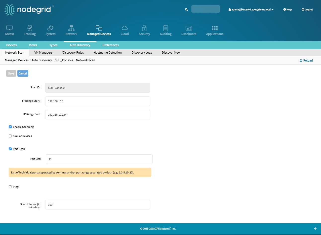
Create Discovery Rule
- Navigate to
Managed Devices:: Auto Discovery:: Discovery Rules - click on
Addto add a new Discovery Rule - Enter a
Namefor the Discovery Rule - Select a
Statusfor the discovered rule, possible values are: Enabled, Disabled - As
Discovery Methodselect Network Scan - For
Scan IDselect the Network Scan ID which was created - The
Host or VM Identifierparameter can be used to further apply a filter if a value is provided then part of the port name has to match the value - For
Actionselect an action which should be performed when a new device is discovered, possible values are: Clone (Mode:Enabled),Clone (Mode:On-Demand),Clone (Mode:Discovered),Discard discovered Devices - In the
Clone from fieldselect the template device which was created earlier - Click on
Saveto create the rule
- Navigate to
- the Nodegrid Platform will automatically start discovering devices based on the created
Discovery Rules. This process will take a few minutes to complete.
Auto Discovery of Network Devices - CLI
Create Template Device
Navigate to
/settings/devicesuse the
addcommand to create a new deviceuse the
setcommand to define the following settingsnametype, possiable values are: device_console, ilo,imm,drac,idrac6,ipmi1.5,impi2.0,ilom,cimc_ucs,netapp,infrabox,pdu*ip_addressas 127.0.0.1- set
usernameandpassword, or selectAsk During Loginoption if you want to provide user credentials during the login time - set
modeto disabled
save the changes with
commitOptional, settings which controll the display and behavior of the device can be adjusted at this time. See Device Settings for more details.
[admin@nodegrid /]# cd /settings/devices
[admin@nodegrid devices]# add
[admin@nodegrid {devices}]# set name=Network_Template
[admin@nodegrid {devices}]# set type=device_console
[admin@nodegrid {devices}]# set ip_address=127.0.0.1
[admin@nodegrid {devices}]# set credential=ask_during_login

or

[admin@nodegrid {devices}]# set credential=set_now
[admin@nodegrid {devices}]# set username=admin password=admin

[admin@nodegrid {devices}]# set mode=disabled
[admin@nodegrid {devices}]# commit
Create a Network Scan
Navigate to
/settings/auto_discovery/network_scan/use the
addcommand to create a Network Scanuse the
setcommand to define the following settingsscan_identer a name for the Network Scandefine a Network range which should be scanned with
ip_range_startandip_range_endset
enable_scanningto yes to enable the scandefine one or more of the three scan methods:
- to use
similar_devicessetdeviceto match one of the existing devices or templates - to use
port_scansetport_listto a list of ports which should be reachable on the device - to use
pingno further settings are required
- to use
set
scan_intervalwhich can range in minutes
[admin@nodegrid /]# cd /settings/auto_discovery/network_scan/
[admin@nodegrid network_scan]# add
[+admin@nodegrid {network_scan}]# set scan_id=SSH_Console
[+admin@nodegrid {network_scan}]# set ip_range_start=192.168.10.1
[+admin@nodegrid {network_scan}]# set ip_range_end=192.168.10.254
[+admin@nodegrid {network_scan}]# set enable_scanning=yes
[+admin@nodegrid {network_scan}]# set similar_devices=yes
[+admin@nodegrid {network_scan}]# set device= network_template
[+admin@nodegrid {network_scan}]# set port_scan=yes
[+admin@nodegrid {network_scan}]# set port_list=22
[+admin@nodegrid {network_scan}]# set ping=no
[+admin@nodegrid {network_scan}]# set scan_interval=100
[+admin@nodegrid {network_scan}]# commit
Create Discovery Rule
Navigate to
/settings/auto_discovery/discovery_rules/use the
addcommand to create a Discovery Ruleuse the
setcommand to define the following settingsrule_namefor the Discovery Rulestatusfor the discovered rule, possible values are: enabled, disabledmethodset to network_scanscan_idselect a Network Scan ID which was created earlierhost_identifierparameter can be used to further apply a filter if a value is provided then part of the port name has to match the value
For
actionselect an action which should be performed when a new device is discovered, possible values are: clone_mode_enabled,clone_mode_on-demand,clone_mode_discovered,discard_deviceclone_fromset to the template device which was created earliersave the changes with
commit
[admin@nodegrid /]# cd /settings/auto_discovery/discovery_rules/
[admin@nodegrid discovery_rules]# add
[admin@nodegrid {discovery_rules}]# set rule_name=Network_Scan
[admin@nodegrid {discovery_rules}]# set status=enabled
[admin@nodegrid {discovery_rules}]# set method=network_scan
[admin@nodegrid {discovery_rules}]# set scan_id=SSH_Console
[admin@nodegrid {discovery_rules}]# set action=clone_mode_enabled
[admin@nodegrid {discovery_rules}]# set clone_from=Network_Template
[admin@nodegrid {discovery_rules}]# commit
- The Nodegrid Platform will automatically start discovering devices based on the created
Discovery Rules. This process will take a few minutes to complete.
Auto Discovery of Virtual Machines
Virtual Machines which are managed by VMWare VCenter or run on ESXi can be discovered and managed. The process will regularly scan VCenter or the ESXi host and detect newly added Virtual Machines. The virtual machines can either be added as type virtual_console_vmware or virtual_serial_port. See Appendix A: Configuring Virtual Serial Port (vSPC) on VM Servers
Note: ESXi free version is not supported.
Auto Discovery of Virtual Machines - WebUI
Create Template Device
- Navigate to
Managed Devices:: Devices - click the
Addbutton to add a device to the system. - Enter a name of the template you want to add
- Enter 127.0.0.1 for the IP address
- In the
Typefield, select a type that matches the Virtual Machine type. Possible values are: virtual_console_vmware - Enter
usernameandpassword, or selectAsk During Loginoption if you want to provide user credentials during the login time - Select as
ModeDisabled, this will ensure that the device is not displayed in the access page - click the Save button.
- Optional, settings which control the display and behaviour of the device can be adjusted at this time. See Device Settings for more details.
- Navigate to
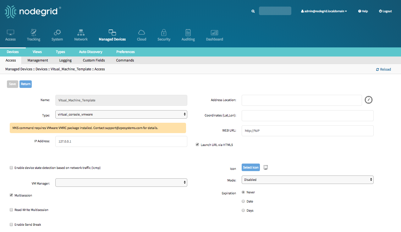
Create Discovery Rule
- Navigate to
Managed Devices:: Auto Discovery:: Discovery Rules - click on
Addto add a new Discovery Rule - Enter a
Namefor the Discovery Rule - Select a
Statusfor the discovered rule, possible values are: Enabled, Disabled - As
Discovery Methodselect VM Manager - Optional use the fields
DatacenterandClusterto filter the scan to these specific entries - The
Host or VM Identifierparameter can be used to further apply a filter if a value is provided then part of the port name has to match the value - For
Actionselect an action which should be performed when a new device is discovered, possible values are: Clone (Mode:Enabled),Clone (Mode:On-Demand),Clone (Mode:Discovered),Discard discovered Devices - In the
Clone from fieldselect the template device which was created earlier - Click on
Saveto create the rule
- Navigate to
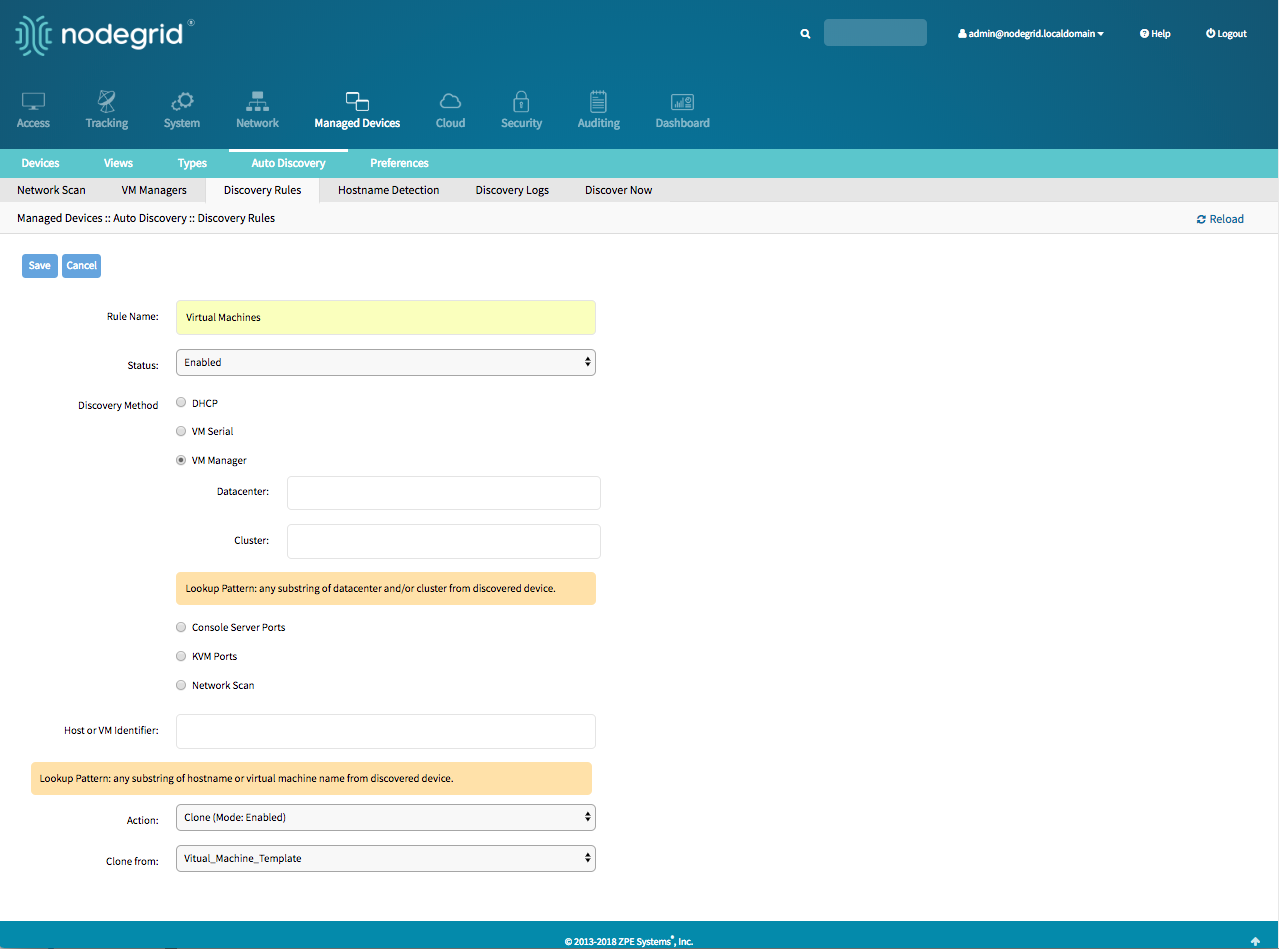
Define a VM Manager
- Navigate to
Managed Devices :: Auto Discovery :: VM Managers - Click on
Addto define a new VM Manager - Provide the VCenter/ESXi IP or FQDN in
VM Serverfield - define the
UsernameandPasswordfor the server - adjust the
HTML console portif needed - Click on
Save
- Navigate to
Enable Discover Virtual Machines
- Nodegrid platform will connect now to the VCenter or ESXi system, this can take a few minutes
- Click on the newly created and connected
VM Manager - Enable
Discover Virtual Machinesoption to configure the Virtual Machine discovery option, define as a minimum aData CenterandDiscovery Polling Interval. - Click on
Save
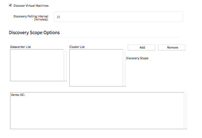
Auto Discovery of Virtual Machines - CLI
Create Template Device
Navigate to
/settings/devicesuse the
addcommand to create a new deviceuse the
setcommand to define the following settingsnametype, possiable values are: virtual_console_vmwareip_addressas 127.0.0.1- set
modeto disabled
save the changes with
commitOptional, settings which controll the display and behavior of the device can be adjusted at this time. See Device Settings for more details.
[admin@nodegrid /]# cd /settings/devices
[admin@nodegrid devices]# add
[admin@nodegrid {devices}]# set name=Virtual_Machine_Template
[admin@nodegrid {devices}]# set type=virtual_console_vmware
[admin@nodegrid {devices}]# set ip_address=192.168.2.151
[admin@nodegrid {devices}]# set mode=disabled
[admin@nodegrid {devices}]# commit
Create Discovery Rule
Navigate to
/settings/auto_discovery/discovery_rules/use the
addcommand to create a Discovery Ruleuse the
setcommand to define the following settingsrule_namefor the Discovery Rulestatusfor the discovered rule, possiable values are: enabled, disabledmethodset to vm_manager- use
datacenterandclusterto define filters based on Data Center and or Cluster host_identifierparameter can be used to further apply a filter, if a value is provided then part of the port name has to match the value
For
actionselect an action which should be performed when a new device is discovered, possiable values are: clone_mode_enabled,clone_mode_on-demand,clone_mode_discovered,discard_deviceclone_fromset to the template device which was created earliersave the changes with
commit
[admin@nodegrid /]# cd /settings/auto_discovery/discovery_rules/
[admin@nodegrid discovery_rules]# add
[admin@nodegrid {discovery_rules}]# set rule_name=Virtual_Machine
[admin@nodegrid {discovery_rules}]# set status=enabled
[admin@nodegrid {discovery_rules}]# set method=vm_manager
[admin@nodegrid {discovery_rules}]# set action=clone_mode_enabled
[admin@nodegrid {discovery_rules}]# set clone_from=Vitual_Machine_Template
[admin@nodegrid {discovery_rules}]# commit
Define a VM Manager
Navigate to
/settings/auto_discovery/vm_managers/use the
addcommand to create a VM Manageruse the
setcommand to define the following settingsvm_server: Provide the VCenter/ESXi IP or FQDN- define
usernameandpassword - adjust the
html_console_portif needed
save the changes with
commit
xxxxxxxxxx[admin@nodegrid /]# cd /settings/auto_discovery/vm_managers/[admin@nodegrid vm_managers]# add[admin@nodegrid {vm_managers}]# set vm_server=VCenter[admin@nodegrid {vm_managers}]# set username=admin[admin@nodegrid {vm_managers}]# set password=password[admin@nodegrid {vm_managers}]# commit
Enable Discover Virtual Machines
- Nodegrid platform will connect now to the VCenter or ESXi system, this can take a few minutes
- Click on the newly created
VM Manager - Enable
Discover Virtual Machinesoption to configure the Virtual Machine discovery option, define as a minimum aData CenterandDiscovery Polling Interval. - Click on
Save
xxxxxxxxxx[admin@nodegrid 192.168.2.217]# showvm server: 192.168.2.217username = Administrator@zpesystems.compassword = ********type = VMwarehtml_console_port = 7331,7343discover_virtual_machines = yesinterval_in_minutes = 15discovery_scope = Demo-DC!
Auto Discovery of DHCP Clients
The Nodegrid Platform can be used as a DHCP Server for Clients within the management network. These devices can be automatically discovered and added to the Nodegrid platform. This feature only supports DHCP Clients which receive their DHCP lease from the local Nodegrid platform, see DHCP Server for details on how to setup the DHCP Server feature.
Auto Discovery of DHCP Clients - Web UI
Create Template Device
- Navigate to
Managed Devices:: Devices - click the
Addbutton to add a device to the system. - Enter a name of the template you want to add
- Enter 127.0.0.1 for the IP address
- In the
Typefield, select a type that matches desired device type. - Enter
usernameandpassword, or selectAsk During Loginoption if you want to provide user credentials during the login time - Select as
ModeDisabled, this will ensure that the device is not displayed in the access page - click the Save button.
- Optional, settings which control the display and behaviour of the device can be adjusted at this time. See Device Settings for more details.
- Navigate to
Create Discovery Rule
- Navigate to
Managed Devices:: Auto Discovery:: Discovery Rules - click on
Addto add a new Discovery Rule - Enter a
Namefor the Discovery Rule - Select a
Statusfor the discovered rule, possible values are: Enabled, Disabled - As
Discovery Methodselect DHCP - Optional use the field
MAC Addressto filter to these specific entries - The
Host or VM Identifierparameter can be used to further apply a filter if a value is provided then part of the port name has to match the value - For
Actionselect an action which should be performed when a new device is discovered, possible values are: Clone (Mode:Enabled),Clone (Mode:On-Demand),Clone (Mode:Discovered),Discard discovered Devices - In the
Clone from fieldselect the template device which was created earlier - Click on
Saveto create the rule
- Navigate to
After the rule was created will device be automatically added to the system as soon as they receive an DHCP address or renew there DHCP address lease, default value for the address lease renewal is every 10min.
Auto Discovery of DHCP Clients - CLI
Create Template Device
Navigate to
/settings/devicesuse the
addcommand to create a new deviceuse the
setcommand to define the following settingsnametype, possiable values are: device_console, ilo,imm,drac,idrac6,ipmi1.5,impi2.0,ilom,cimc_ucs,netapp,infrabox,pdu*ip_addressas 127.0.0.1- set
usernameandpassword, or selectAsk During Loginoption if you want to provide user credentials during the login time - set
modeto disabled
save the changes with
commitOptional, settings which controll the display and behavior of the device can be adjusted at this time. See Device Settings for more details.
[admin@nodegrid /]# cd /settings/devices
[admin@nodegrid devices]# add
[admin@nodegrid {devices}]# set name=Network_Template
[admin@nodegrid {devices}]# set type=device_console
[admin@nodegrid {devices}]# set ip_address=127.0.0.1
[admin@nodegrid {devices}]# set credential=ask_during_login

or

[admin@nodegrid {devices}]# set credential=set_now
[admin@nodegrid {devices}]# set username=admin password=admin

[admin@nodegrid {devices}]# set mode=disabled
[admin@nodegrid {devices}]# commit
Create Discovery Rule
Navigate to
/settings/auto_discovery/discovery_rules/use the
addcommand to create a Discovery Ruleuse the
setcommand to define the following settingsrule_namefor the Discovery Rulestatusfor the discovered rule, possible values are: enabled, disabledmethodset to dhcp- Optional, use the
mac_addressfield to filter to these specific entries host_identifierparameter can be used to further apply a filter if a value is provided then part of the port name has to match the value
For
actionselect an action which should be performed when a new device is discovered, possible values are: clone_mode_enabled,clone_mode_on-demand,clone_mode_discovered,discard_deviceclone_fromset to the template device which was created earliersave the changes with
commit
xxxxxxxxxx[admin@nodegrid /]# cd /settings/auto_discovery/discovery_rules/[admin@nodegrid discovery_rules]# add[admin@nodegrid {discovery_rules}]# set rule_name=Network_Scan[admin@nodegrid {discovery_rules}]# set status=enabled[admin@nodegrid {discovery_rules}]# set method=dhcp[admin@nodegrid {discovery_rules}]# set mac_address=00:0C:29[admin@nodegrid {discovery_rules}]# set action=clone_mode_enabled[admin@nodegrid {discovery_rules}]# set clone_from=Network_Template[admin@nodegrid {discovery_rules}]# commit
Device Settings
Most devices support additional configuration options and settings. This section will explain these settings and how they can be configured.
Hostname Detection
This feature allows the automatic discovery of a target devices hostnames (network or serial), base on its login prompt, promt or a banner.
By default, it has already some probes and matches for most of following devices types: PDUs, NetApp, Console Servers, Device Consoles, and Service Processors.
Nodegrid will send the first probe, and wait for a match. If there is no match, it will send the second probe, and so on. Once there is a match, the probing stops for that device.
Configure Hostname Detection
In most case the only configuration required is to enable the feature on the target device. For this navigate to the device in the Managed Devices (WebUI) or settings/devices/ (CLI) section and enable the feature.
WebUI
- Navigate to
Managed Devices:: Devices - Click on the Target Device to access its settings
- Tick the box besides
Enable Hostname Detection - Save the settings
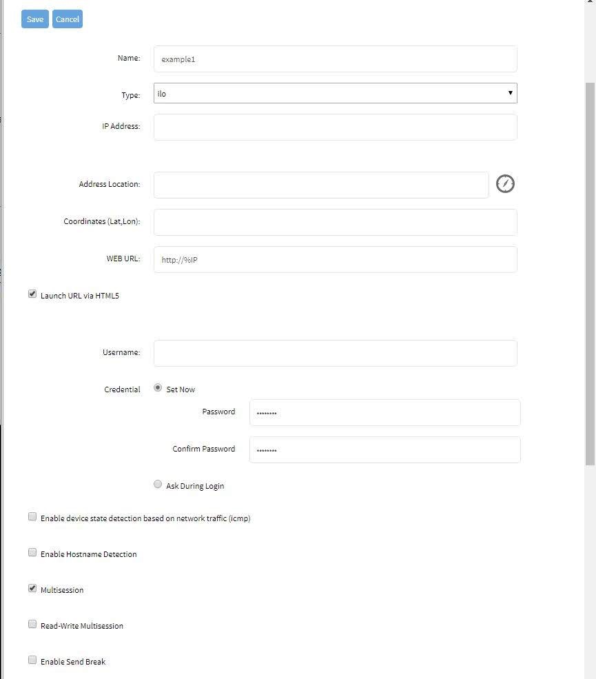
CLI
- Navigate to
/settings/devices/<Device Name>/access - set
enable_hostname_detectionto yes - Commit the changes
[admin@nodegrid /]# /settings/devices/Device_Console_Serial/access/
[admin@nodegrid /]# set enable_hostname_detection=yes
[+admin@nodegrid /]# commit
Global Settings for Hostname Detection
Futher, to enabling the feature for each target device can the following settings be adjusted under Managed Devices:Auto Discovery:Hostname Detection (WebUI) or /settings/auto_discovery/hostname_detection (CLI)
The following global settings can be configured
- Probe timeout: Timeout in secounds which the Nodegrid will wait for a output after the probe was send
- Number of retries: The amount of times the probes will be resent to the device if no output was available
- Discovered name updates device name: This setting is enabled by default, by disabling it no devices names will be updated even if a match was found.
- New discovered device receives the name during conflict: This option can be enabled. In case multiple devices have the same name then the latestdevice discovered with this name will receive the name.
- Probe: is String (Text) combinations of characters send to the device. The output is then matched against the existing Match Strings. Existing probes can be adjusted or new probes created.
- Match: is RegEx expressions, which are matched against the probes output. In case a match is found the hostname will be extracted and the device name updated. Existing matches can be adjusted and new matches created.
General Settings
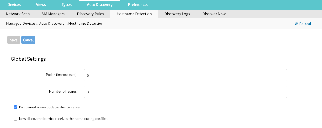
Create a Probe or Match
WebUI
- Navigate to
Managed Devices:Auto Discovery:Hostname Detection - Click on Add
- Select a value from
String Type - Provide a String which will be the Match or Probe.
Note: For Matches RegEx expressions are allowed. Use the variable
%Hto indicate the loaction of the hostname
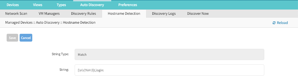
CLI
Navigate to
/settings/auto_discovery/hostname_detection/string_settingstype
adduse the
setcommand to definestring_typeas either match or probeuse the
setcommand to define a probe or match stringActive and save the change with
commitNote: For Matches RegEx expressions are allowed. Use the variable
%Hto indicate the loaction of the hostname
Multi Sessions
Multisessions allow multiple users to access the same device at the same time. All users will be able to see the same output. By default the first user has read-write access, all other users have read access to the session. By enabling the option Read-Write Multisession can this behavior be changed so that all connected users have read-write access to the session. In this case only one user at a time has write access, the system automatically switches to the first user who is trying to enter keystrokes in the session.
It is possiable to see during a session all connected users through the console session menu (see: Break Signal). This feature is available for device console sessions.
WebUI
- Navigate to
Managed Devices:: Devices - Click on the Target Device to access its settings
- Tick the box besides
Multisessions - Optional: Tick the box besides
Read-Write Multisession - Save the settings
CLI
- Navigate to
/settings/devices/<Device Name>/access - set
multisessionto yes - Optional: set
write_multisessionto yes committhe changes
xxxxxxxxxx[admin@nodegrid /]# /settings/devices/Device_Console_Serial/access/[admin@nodegrid /]# set multisession=yes[+admin@nodegrid /]# set read-write_multisession=yes[+admin@nodegrid /]# commitBreak Signal
This options allows users to send a break signal via the ssh console session. The function can be enabled on a per device basis and the break sequence be set.
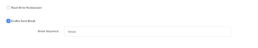
WebUI
- Navigate to
Managed Devices:: Devices - Click on the Target Device to access its settings
- Tick the box besides
Enable Send Break - Adjust the
Break Sequenceas needed
CLI
- Navigate to
/settings/devices/<Device Name>/access - set
enable_send_breakto yes - adjust
break_sequenceas needed committhe changes
[admin@nodegrid /]# /settings/devices/Device_Console_Serial/access/
[admin@nodegrid /]# set enable_send_break=yes
[+admin@nodegrid access]# set break_sequence=~break
[+admin@nodegrid access]# commit
Escape Sequences
Escape Sequences allow users to esacpe from the current session and to bring up a menu or to directly perform specific tasks like bring up the power menu.
The Nodegrid supports two escape sequences. One for the normal session menu and secound for the power menu which allows for direct power controll of a target device if this is setup accordingly. (See: Power Control)
Both escape sequences are preset with a default value which can be changed if needed.
| Default Sequence | ||
|---|---|---|
| Escape Sequence | ^Ec | CTRL+SHIFT+E c |
| Power Control Key | ^O | CTRL+SHIFT+O |
WebUI
- Navigate to
Managed Devices:: Devices - Click on the Target Device to access its settings
- Adjust the
Escape SequenceorPower Control Keyas needed
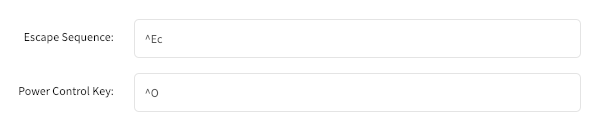
CLI
- Navigate to
/settings/devices/<Device Name>/access - Adjust the
escape_sequenceorpower_control_keyas needed committhe changes
[admin@nodegrid /]# /settings/devices/Device_Console_Serial/access/
[admin@nodegrid /]# set escape_sequence=^Ec
[+admin@nodegrid access]# set power_control_key=^O
[+admin@nodegrid access]# commit
Disable User Authentication
By default when accessing a target device, the user has to authenticate first against the Nodegrid unit and is then connected through to the device. If this is not required for a specific reason then this features allows to disable the Nodegrid authentication for the specific devices.
Note: This will disable any Nodegrid authentication methond for this device. Ensure that appropiate authentication menchanism are setup on the target device.
WebUI
- Navigate to
Managed Devices:: Devices - Click on the Target Device to access its settings
- Tick the box besides
Skip authentication to access device (NONE authentication)
CLI
- Navigate to
/settings/devices/<Device Name>/access - Set the
skip_authentication_to_access_deviceto yes to disable authentication committhe changes
[admin@nodegrid /]# /settings/devices/Device_Console_Serial/access/
[admin@nodegrid /]# set skip_authentication_to_access_device=yes
[+admin@nodegrid access]# commit
SSH / Telnet Port
This features allows administrors to define a specific ssh or telnet port for target devices.
By default each target device has a unique telnet port assign which uses port 7000 as basis port plus the port number. For ssh connections the default port will be used for all connections by default.
SSH and Telnet ports ports can be adjusted as needed.
WebUI
Navigate to
Managed Devices:: DevicesClick on the Target Device to access its settings
Tick the box besides
Allow SSH protocolorAllow Telnet protocol.Note: Both options are enabled by default.
- provide or adjust the port number as needed
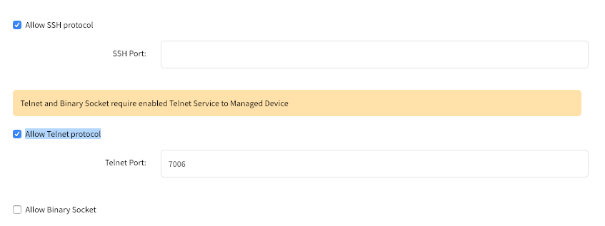
CLI - SSH
- Navigate to
/settings/devices/<Device Name>/access - use the
setcommand setallow_ssh_protocolto yes - use the
setcommand to define assh_portnumber committhe changes
CLI - Telnet
- Navigate to
/settings/devices/<Device Name>/access - use the
setcommand setallow_telnet_protocolto yes - use the
setcommand to define atelnet_portnumber committhe changes
[admin@nodegrid /]# /settings/devices/Device_Console_Serial/access/
[admin@nodegrid /]# set allow_ssh_protocol=yes
[+admin@nodegrid access]#set ssh_port=17001
[+admin@nodegrid access]#set allow_telnet_protocol=yes
[+admin@nodegrid access]#set telnet_port=7001
[+admin@nodegrid access]#commit
Binary Socket
The Binary Socket Feature allows for 3rd party systems to directly access the device as if it would be physically connected. Singals will be transmitted directly and will not be encapsulated in the telnet or ssh protocol. A specific port needs to be assigned.
WebUI
- Navigate to
Managed Devices:: Devices - Click on the Target Device to access its settings
- Tick the box besides
Allow Binary Socket - provide or adjust the port number as needed
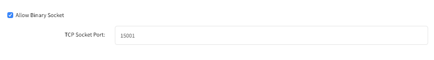
CLI
- Navigate to
/settings/devices/<Device Name>/access - use the
setcommand setallow_binary_socketto yes - use the
setcommand to define atcp_socket_portnumber committhe changes
[admin@nodegrid /]# /settings/devices/Device_Console_Serial/access/
[admin@nodegrid /]# set allow_binary_socket=yes
[+admin@nodegrid access]#set tcp_socket_port=15001
[+admin@nodegrid access]#commit
IP Aliases
Console sessions can be started from the WebUI, CLI or directly through a ssh/telnet client. In case a ssh client is used the default method to access a specific target device is to pass the target device name through as a parameter.
Port Aliases allow users to connect instead to a target device by utilising a IP Addresses. Each IP Alias supports the definition of a telnet and binary port as desired
The Nodegrid solution supports the allocation of upto 2 IP address alias for each target device. The feature supports IPv4 as well as IPv6 Addresses.
WebUI
Navigate to
Managed Devices:: DevicesClick on the Target Device to access its settings
Tick the box besides
Enable IP AliasProvide a valid IP address
Select a vaild network interface through which the IP address will be accessible.
Allow the Telnetprotocol for the interface if desired- Adjust the port if desired
Allow Binary Socketfor direct access if desired- Adjust the port if desired
Repeat these steps for
Enable Second IP Alias
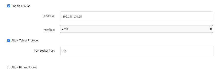
CLI
Navigate to
/settings/devices/<Device Name>/accessuse the
setcommand setenable_ip_aliasto yesuse the
setcommand to define the following values as required- ip_alias - IP address
- interface - Network interface to be used
- ip_alias_telnet - Enable/Disable telnet
- ip_alias_telnet_port - Telnet port to be used
- ip_alias_binary - If the interface should support binary soocket connections
repeat these steps for
enable_second_ip_aliascommitthe changes
[admin@nodegrid /]# /settings/devices/Device_Console_Serial/access/
[admin@nodegrid /]# set enable_ip_alias=yes
[+admin@nodegrid access]#set ip_alias=192.168.10.249
[+admin@nodegrid access]#set interface=eth0
[+admin@nodegrid access]#set ip_alias_telnet=yes
[+admin@nodegrid access]#set ip_alias_telnet_port=23
[+admin@nodegrid access]#set ip_alias_binary=no
[+admin@nodegrid access]#set ip_alias_binary_port=15001
[+admin@nodegrid access]#commit
Location
Each Device can be assosiated with a location. The location details are used to display the device and its status on the map view.
The location can be defined through address details or directly through Longitude and Latitude values. In case the location values are provided through an address dose the unit require a internet connection, for the translation into longitude and latitude.
WebUI
- Navigate to
Managed Devices:: Devices - Click on the Target Device to access its settings
- Provide a address in the
Address Locationfield and press the loactor icon to the right to identify the latitude and longitude coordinates. - Alternatively directly provide valid latitude and longitude coordinates
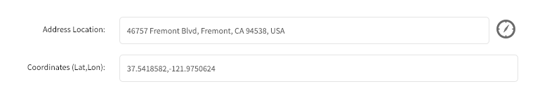
CLI
Note: The CLI dose not support the function to look up a address and convert it to valid latitude and longitude coordinates.
- Navigate to
/settings/devices/<Device Name>/access - use the
setcommand to provide valid latitude and longitude coordinates - Alternatively provide an address
[admin@nodegrid /]# /settings/devices/Device_Console_Serial/access/
[admin@nodegrid /]# set coordinates="37.5418582,-121.9750624"
[+admin@nodegrid access]#set address_location="46757 Fremont Blvd, Fremont, CA 94538, USA"
[+admin@nodegrid access]#commit
Web URL
A Web URL can be defined for each device. The URL will be used for the Web command which is available for each device by default.
The defaut URL defined for all IP based sessions is http://%IP where by %IP will be replaced by the IP Address values defined for each device.
By default will the URL be opened inside a HTML5 frame which is forwarded to the client. This allows to pass through unsewcured device web interfaces without exposing the devices to the network.
This can be controlled by disabling the feature Launch URL via HTML5
WebUI
- Navigate to
Managed Devices:: Devices - Click on the Target Device to access its settings
- Adjust the
WEB URLvalue as needed - Enable or Disable the launch of the URL in HTML5 window as needed by setting
Launch URL via HTML5
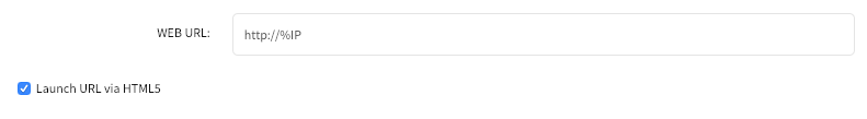
CLI
- Navigate to
/settings/devices/<Device Name>/access - use the
setcommand to adjust theweb_url - enable or disable the launch of the URL in HTM5 window by setting
launch_url_via_html5
[admin@nodegrid /]# /settings/devices/Device_Console_Serial/access/
[admin@nodegrid /]#set web_url="https://%IP"
[+admin@nodegrid access]#set launch_url_via_html5=yes
[+admin@nodegrid access]#commit
Icon
For each device can a icon be defined, which reptresents its device type.
WebUI
- Navigate to
Managed Devices:: Devices - Click on the Target Device to access its settings
- Adjust the device icon by click on
Select Iconand selecting the desired icon
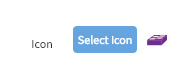
CLI
- Navigate to
/settings/devices/<Device Name>/access - use the
setcommand to adjust theiconto a valid value. Use tab-tab at this point to see a list a valud values. committhe changes
[admin@nodegrid /]# /settings/devices/Device_Console_Serial/access/
[admin@nodegrid /]#set icon=switch.png
[+admin@nodegrid access]#commit
Mode
The device Mode defines how the device is managed by the Nodegrid platform and how the device status is confirmed. The system supports 4 different modes.
| Mode | Description |
|---|---|
| Disabled | In this mode is a device disabled. No sessions can be opened to it and Nodegrid dose not check if the device is reachable. |
| Enabled | In this mode is a device enabled and sessions can be started. Nodegrid activly checks if a device is reachable. |
| On-Demand | In this mode is a device enabled and session can be started. Nodegrid dose not check if a device is reachable |
| Discovered | In this mode is a device disabled. No sessions can be opened to it and Nodegrid dose not check if the device is reachable. This mode indicates that the device was added to the system through a discovery process. |
WebUI
Navigate to
Managed Devices:: DevicesClick on the Target Device to access its settings
Set the device mode by selecting a valid mode from the drop-down list
Note: Discovered can not be selected as this is a system status only
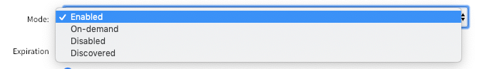
CLI
Navigate to
/settings/devices/<Device Name>/accessuse the
setcommand to adjust themodeto either- enabled
- disabled
- on-demand
committhe changes
[admin@nodegrid /]# /settings/devices/Device_Console_Serial/access/
[admin@nodegrid /]#set mode=enabled
[+admin@nodegrid access]#commit
Expiration
For each device can a expiration date or days be defined after which a device will automatically become unavailable. The default value is Never in which case the device and its data will stay in the system until
admin user removes it.
Date – the device will be available until the date specified. After that date, it will set to Disabled mode and admin user has 10 days to take an action. After the 10 days, the device and its data will be removed from the system.
Days – this is similar to timeout – if there is no update on the device’s configuration, after the specified days, the device and its data will be removed from the system. This is independent of the use of the device.
Both Date and Days will be mostly applied to VM devices in order to get in sync with the ESXi Servers where the VMs are constantly being added, moved, and deleted, and the Nodegrid managed device license may become available.
NOTE: This feature is only available for IP based devices
WebUI
Navigate to
Managed Devices:: DevicesClick on the Target Device to access its settings
Select either
Never,Expiration DateorExpiration Daysand provide an appropiate value.- Date: Dates need to be provided in the format of YEAR-MONTH-DAY (YYYY-MM-DD)
- Days: value has to be between 1 and 9999999999
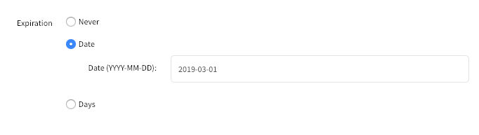
CLI
Navigate to
/settings/devices/<Device Name>/accessuse the
setcommand to adjust theexpirationto eitherneverdate- use the
setcommand to provide a valid expiration date inexpiration_date
- use the
days- use the
setcommand to provide a valid number of days between 0 and 9999999999 inexpiration_days
- use the
committhe changes
[admin@nodegrid /]# /settings/devices/Device_Console_Serial/access/
[admin@nodegrid /]#set expiration=date
[+admin@nodegrid access]#set expiration_date=2020-01-01
[+admin@nodegrid access]#commit

or

[admin@nodegrid /]#set expiration=days
[+admin@nodegrid access]#set expiration_days=5
[+admin@nodegrid access]#commit

or

[admin@nodegrid /]#set expiration=never
Device State Detection
Nodegrid supports for all devices which are in enabled mode a device state deticetion which indicates if the device is currently available.
Serial Devices
By default uses Nodegrid for serial devices the DCD or CTS signals. In case these signal do not exist for a specific device can the device state detection be changed to use the data flow instead. In this case the state will be determent based on actaul data be transmitted by the device.
To use this feature the function Enable device state detection based in data flow needs to be enabled
IP Devices
The default mechanism for IP based devices is to establish and monitore an active ssh session to a device.
Additionally to this can a icmp (ping) check be enabled to establish if the device is active.
To use this feature the function Enable device state detection based on network traffic (icmp) needs to be enabled
WebUI
Navigate to
Managed Devices:: DevicesClick on the Target Device to access its settings
Enable device state detection by ticking the box
for serial:
Enable device state detection based in data flow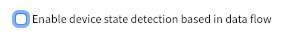
for other devices:
Enable device state detection based on network traffic (icmp)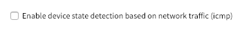
CLI
Navigate to
/settings/devices/<Device Name>/accessuse the
setcommand to to enable the device state detection- for serial:
enable_device_state_detection_based_in_data_flow - for other devices:
enable_device_state_detection_based_on_network_traffic
- for serial:
committhe changes
[admin@nodegrid /]# /settings/devices/Device_Console_Serial/access/
[admin@nodegrid /]#set enable_device_state_detection_based_in_data_flow=yes

or

[admin@nodegrid /]#set enable_device_state_detection_based_on_network_traffic=yes

[+admin@nodegrid access]#commit
Run Custom Scripts on Device Status Change
This feature allows users to assigned custom scripts to specific device status changes. This feature is mostly used in cases specific actions need to be performed on status changes which go bejond event notifications.
The following status changes can be used:
- Session Start
- Session Stop
- Device Up
- Device Down
The scripts need to be written and provided either by the customer or through a Proffessional Services engagment.
The scripts need to be copied to the Nodegrid before they can be assigned to a device status. Scripts need to be placed in the /etc/scripts/access folder. Each script needs to to be executable with user privileges.
WebUI
Navigate to
Managed Devices:: DevicesClick on the Target Device to access its settings and Navigate to
ManagmentIn the
Scriptssection assign available scripts to a device statusRun on Session StartRun on Session StopRun on Device UPRun on Device Down
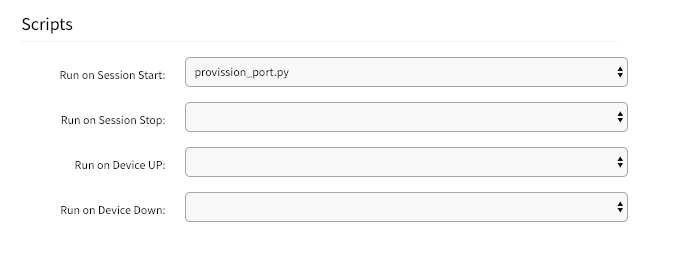
CLI
Navigate to
/settings/devices/<Device Name>/managmentuse the
setcommand to assign a script to a device statuson_session_starton_session_stopon_device_upon_device_down
committhe changes
[admin@nodegrid /]# /settings/devices/Device_Console_Serial/management/
[admin@nodegrid /]#set on_session_start=sessionstart.sh
[+admin@nodegrid management]#commit
Data Logging
Note: This feature is available to all text based sessions, like serial sessions or ssh based sessions.
Through enabling of the Data Log feature will the system be configured to collect data logs from a device. Data logs will capture all information which are send to a device and and are coming from a device. If a device is in enabled mode will the data logs collect data even if no user is currently connect to device. This enables logging of system messages which are pushed to console sessions.
The collected data logs will be stored locally to the Nodegrid or remotly depending on the Auditing settings.
WebUI
- Navigate to
Managed Devices:: Devices - Click on the Target Device to access its settings and Navigate to
Logging - Enable the option
Data Logging
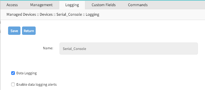
CLI
- Navigate to
/settings/devices/<Device Name>/logging - use the
setcommand to change thedata_loggingvalue toyesorno committhe changes
[admin@nodegrid /]# /settings/devices/Device_Console_Serial/logging/
[admin@nodegrid /]#set data_logging=yes
[+admin@nodegrid logging]#commit
Event Logging
Note: This feature is available to Service Processor and IPMI sessions.
By enabling this feature will the system be configured to collcet Service Processor Event Log data. The type of collected data will depend on the abilties and configuration of the Service Process.
With the settings Log Frequency and Log unit can be controlled how often the information can be collected. Collection intervals range from 1 min to 9999 hours.
The collected data logs will be stored locally to the Nodegrid or remotly depending on the Auditing settings.
WebUI
- Navigate to
Managed Devices:: Devices - Click on the Target Device to access its settings and Navigate to
Logging - Enable the option
Event Logging - Adjust the values for
Event Log FrequecyorEvent Log Unitas needed
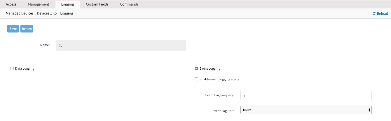
CLI
Navigate to
/settings/devices/<Device Name>/logginguse the
setcommand to change theevent_loggingvalue toyesornouse the
setcommand to adjustevent_log_frequecyandevent_log_unitas neededevent_log_frequecyrange from 1 - 9999event_log_unitoptionshoursorminutes
committhe changes
[admin@nodegrid /]# /settings/devices/ipmi/logging/
[admin@nodegrid /]#set event_logging=yes
[+admin@nodegrid logging]#set event_log_frequecy=1
[+admin@nodegrid logging]#set event_log_unit=hours
[+admin@nodegrid logging]#commit
Alert Strings and Custom Scripts
The Data and Event Logging features can additionally to collecting information as well create event notifications and based on these events execute custom scripts. This is archived by defining alert strings. Alert strings can be a simple text match or a regular expression pattern string that is evaluated against the data source stream as the data is collected. Events are generated for each match.
The scripts need to be written and provided either by the customer or through a Proffessional Services engagment.
The scripts need to be copied to the Nodegrid before they can be assigned to a device status. Scripts need to be placed in the /etc/scripts/datalog folder for data log events or /etc/scripts/events folder for event logs. Each script needs to to be executable with user privileges.
WebUI - Data Logging Alerts
Navigate to
Managed Devices:: DevicesClick on the Target Device to access its settings and Navigate to
LoggingEnable the option
Data LoggingEnable the option
Enable data logging alertsDefine a min of one
Data Stringwhich will be matched against the data streamSelect a available script for the defined
Data Scriptin case a custom script should be executed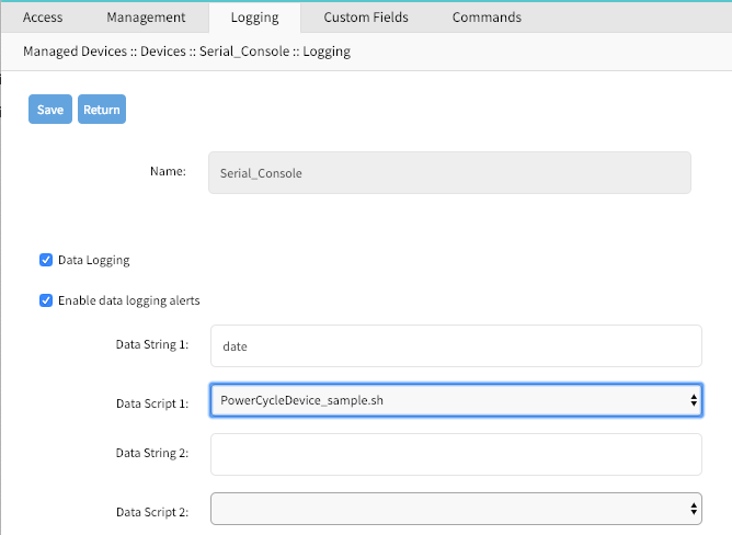
WebUI - Event Logging Alerts
Navigate to
Managed Devices:: DevicesClick on the Target Device to access its settings and Navigate to
LoggingEnable the option
Event LoggingEnable the option
Enable event logging alertsDefine a min of one
Event Stringwhich will be matched against the data streamSelect a available script for the defined
Event Scriptin case a custom script should be executed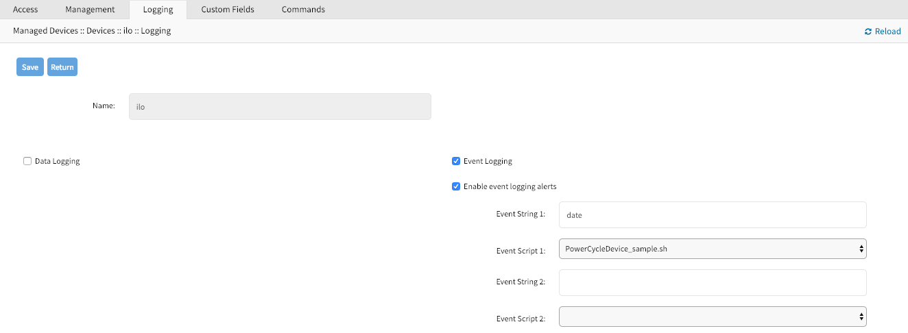
CLI - Data Logging Alerts
- Navigate to
/settings/devices/<Device Name>/logging - use the
setcommand to change thedata_loggingvalue toyes - use the
setcommand to change theenable_data_logging_alertsvalue toyes - define for
data_string_1string or regular expression which will be matched against the data stream - define for
data_script_1a available script in case a custom script should be executed committhe changes
[admin@nodegrid /]# /settings/devices/Device_Console_Serial/logging/
[admin@nodegrid /]#set data_logging=yes
[+admin@nodegrid logging]#set enable_data_logging_alerts=yes
[+admin@nodegrid logging]#set data_string_1="String"
[+admin@nodegrid logging]#set data_script_1=ShutdownDevice_sample.sh
[+admin@nodegrid logging]#commit
CLI - Event Logging Alerts
Navigate to
/settings/devices/<Device Name>/logginguse the
setcommand to change theevent_loggingvalue toyesuse the
setcommand to adjustevent_log_frequecyandevent_log_unitas neededevent_log_frequecyrange from 1 - 9999event_log_unitoptionshoursorminutes
use the
setcommand to change theenable_event_logging_alertsvalue toyesdefine for
event_string_1string or regular expression which will be matched against the data streamdefine for
event_script_1a available script in case a custom script should be executedcommitthe changes
[admin@nodegrid /]# /settings/devices/ipmi/logging/
[admin@nodegrid /]#set event_logging=yes
[+admin@nodegrid logging]#set event_log_frequecy=1
[+admin@nodegrid logging]#set event_log_unit=hours
[+admin@nodegrid logging]#set enable_event_logging_alerts=yes
[+admin@nodegrid logging]#set event_string_1="String"
[+admin@nodegrid logging]#set event_script_1=PowerCycleDevice_sample.sh
[+admin@nodegrid logging]#commit
Custom Fields
Custom Fields allow users to assign additional information to devices. These information will be visable for each device in the device overview page and are fully searchable.
Custom infomormation are stored as a key/value pair.
WebUI
Navigate to
Managed Devices:: DevicesClick on the Target Device to access its settings and Navigate to
Custom FieldsClick on
Addto create a new Custom Field- Provide a Field Name
- Provide a Filed Value

CLI
- Navigate to
/settings/devices/<Device Name>/custom_fields - use the
addcommand to create a new custom field - use the
setcommand to define afield_nameandfield_value committhe changes
[admin@nodegrid /]# /settings/devices/Serial_Console/custom_fields/
[admin@nodegrid /]#add
[+admin@nodegrid custom_fields]#set field_name=Custom_Field_Example
[+admin@nodegrid custom_fields]#set field_value="A Value"
[+admin@nodegrid custom_fields]#commit
Commands and Custom Commands
Each device type offers a collection of commands, which allow users to access and interact with a device. The default configuration is sufficent for most users and is therefore the recommended option. If default configuration is not sufficent can admin users disable or change existing commands, add existing commands which are not enabled by default or assign custom commands to a device. Changes made in the Command feature effect all users and should be take with care. If a admin user wishes to not have specific commands available to certain users or groups, this can be accomplished via user and group authorization.
The available commands for a device will be dependen on the device type, for example is KVM command (which enable Service Processor KVM session support) is only available to Service Processor devices while the Outlet command is available to all device types.
Custom Commands are available to all device types and are provided through custom scripts. Custom commands can provide support for a wide range of different functions, startinging from additional session options to specific custom tasks which should be performed on a device.
The scripts need to be written and provided either by the customer or through a Proffessional Services engagment.
Note: While Custom Commands can be executed through the WebUI and CLI, can Custom Commands currently only provide feedback and output to the CLI and not the WebUI
WebUI - Generic
- Navigate to
Managed Devices:: Devices - Click on the Target Device to access its settings and Navigate to
Commands - Click on
Addto and select the Command to associate it to a device - Click on an existing Commands to change, or diasable commands
WebUI - Custom Commands
Navigate to
Managed Devices:: DevicesClick on the Target Device to access its settings and Navigate to
CommandsClick on
Addto and SelectCustom Commands- Select a
Scriptfrom a list of available scripts - Click on Enable to enbaled the specific command
- Adjsut the Command Label to match the command option in the script
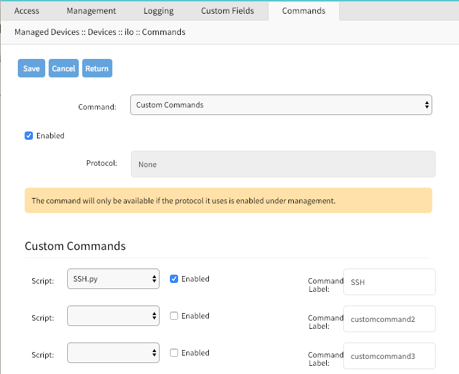
- Select a
CLI - Custom Commands
- Navigate to
/settings/devices/<Device Name>/commands - use the
addcommand to create a new custom field - use the
setcommand to define afield_nameandfield_value committhe changes
[admin@nodegrid /]# /settings/devices/Serial_Console/commands/
[admin@nodegrid /]#add
[+admin@nodegrid commands]#set command=custom_commands
[+admin@nodegrid commands]#set custom_command_enabled1=yes
[+admin@nodegrid commands]#set custom_command_script1=SSH.py
[+admin@nodegrid commands]#set custom_command_label1=SSH
[+admin@nodegrid commands]#commit
Tree View Settings
In Managed Devices :: Views can an admin adjust and create and tree structure, to which devices can be associated. The feature is usefull in order to reflect specifc organisational or physical structures which help users to find and access there devices.
Further can Groups be used to aggregate monitoring values like a Rack or room level.
Device Types
Device Type settings allow administrators to adjust or create customised versions of existing device types. This is benifical in cases where the default value for a device type dose not match a customers current defauklt values.
By either Cloning, Editing or Deleting existing device types, can these values, like the defauly communication protocol be adjusted as needed. These setting will take effect automatically for all devices which currently utilise the specific device type.
Preferences
The Preference menu allows administrators to define Power Menu and Session Prefernces options further. These are global settings and will effect all sessions.
Power Menu Preferences
The power menu preferences options allow administrators to define the order and labling of the power menu as it appears in a console session.
Session Preferences
The session preference section allows users to define a session Disconnect HotKey for console sessions. This feature is benifical when users typicaly start console sessions from within console sessions, as well called cascaded console session. In this case it can be dificult to exit a specif console session witghout closing all sessions in the chain. The hotkey will provide a user the option to specifically disconnect from a specific amount of the console session within the chain. Starting from the current session working its way back up the chain.
The value is by default undefined.
Tracking
The Tracking features provide information about the system and connected devices like Open Sessions, Event List, Routing Table, System Usage, Discovery Logs, LLDP and Serial Statistics.
Open Sessions
The Open Sessions page provides an overview of connected users and devices sessions.
The Sessions Table menu shows all users actively connected to the system, from where they are connecting from, and for how long.
In the Device Table menu shows information about active device sessions, the amount of connected session and the users which are connected.
If a user has permission based on an authorization group, he/she can terminate sessions.
Event List
The Event List menu provides statistical information on the system events
occurrences. Events can be selected and the current counters reset.
System Usage
The System Usage page presents information about Memory Usage, CPU Usage, and Disk usage for the current system.
Discovery Logs
The Discovery Logs page shows the logs of the discovery processes set on the Managed Devices’ setting for auto discovery.
Network Statistics
The Network statistics page displays network Interface information,LLDP and the Routing Table details.
The Interface page displays the network interface statistics, like state, package counters, collisions, dropped and errors.
The LLDP page shows the devices that are advertising their identity and capabilities on the LAN. You may want to enable LLDP advertising and reception through this connection in your Nodegrid by setting it up in network connections.
The Routing Table page shows the routing rules that Nodegrid follows for the network communications. It also included any static network routes which were added.
Device Statistics
The Devices page shows connection statistics for physically connected devices, like serial and USB devices. The available options will depend on the specific Nodegrid unit.
The Serial Statistics page provides statistical information on the serial ports connectivity such as transmitted and received data, RS232 signals, errors.
The USB devices page provides details about connected USB devices and initialized drivers.
Scheduler
The Scheduler page provides information about scheduled tasks, when they were run, by whom and any events or errors where displayed.
System
The system settings allow the configuration of system specific settings like license keys, general system settings, firmware updates, backup and restore and others.
Licenses
Clicking on "System" brings you straight to the "Licenses" tab. This tab displays all licenses enrolled in this Nodegrid, along with other relevant information, a license key, expiration date, application, etc. The upper right corner shows the number of licenses, used and available. Licenses can be added or deleted in this page. If licenses expire or are deleted, the devices exceeding the total licenses will change status to "unlicensed", but their information will be retained in the system. However, unlicensed devices will not show up in the access page.
A license is required for each managed device for Nodegrid access and control. The required license for each serial port of the Nodegrid is included with the product.
A managed device is any physical or virtual device defined under Nodegrid for access and control.
System Preferences
Main system preferences are configured in this tab.
- Address location and coordinates
- Online help URL
- Session idle timeout
- Login logo image and banner message
- The Utilization rate of serial ports and licenses
- Nodegrid serial console speed, bauds
- Display of dual power supplies
- Network boot parameters and ISO image URL
Address Location
Enter a valid address location for this Nodegrid, and click on the small compass icon/button on the right of this field to populate the "Coordinates" field below with Latitude and Longitude of that address.
The "Help Location" field is an alternate URL location for the user manual. The administrator can download the user manual and post to a specific location reachable by Nodegrid. When the small "Help" icon/button on top right of the Nodegrid WebUI is clicked, a new webpage opens with the file referenced by this URL.
Session Idle Timeout
This is the number of seconds for open sessions to time out due to inactivity; enter a zero value for new sessions to never expire. Configuration changes on this field will be effective for new sessions only. Existing sessions will continue following their timeout value specified at session start. This setting applies to all telnet, SSH, HTTP, HTTPS, and console sessions.
Login logo image
Use this feature to change the logo image to be used on Nodegrid's WebUI login page. The new image file has to be a .png or .jpg and can be uploaded from your local desktop or a remote server (FTP, TFTP, SFTP, SCP, HTTP, and HTTPS). Enter the respective URL format, username and password may be required. <PROTOCOL>://<ServerAddress>/<Remote File>.
After uploading, refresh the browser cache to show the new image.
Login Banner
Nodegrid can be configured to show a login banner on Telnet, SSHv2, HTTP, HTTPs and Console login, to display the user a message before logging into the system. The default banner (below) can be edited and customized by the admin.
Default login banner:
WARNING: This private system is provided for authorized use only and it may be monitored for all lawful purposes to ensure its use. All information including personal information, placed on or sent over this system may be
monitored and recorded. Use of this system, authorized or unauthorized, constitutes consent to monitoring your session. Unauthorized use may subject you to criminal prosecution. Evidence of any such unauthorized use may be used for administrative, criminal and/or legal actions.
Utilization Rate
Click and check respective boxes and enter the desired usage percentage to enable monitoring the utilization rate of licenses and local serial ports. An event will be generated when the percentage is reached. The default value is 90%.
Console Port
Set the baud rate of the local console port. The default value is set to 115,200 bps.
Power Supplies
Displays the state of dual power supplies (ON/OFF) and to enable alarm sound (check the appropriate box) when one power supply go down.
To acknowledge the alarm state, click on Acknowledge Alarm State on the top left of this page System::Preferences.
Network Boot (PXE)
Nodegrid can be set to boot from an ISO image from the network. Enter the unit's IPv4 address and netmask, the ethernet interface to be used (eth0 or eth1), and the URL where the ISO image is http://ServerIPAddress/PATH/FILENAME.ISO
Date and Time
Set the Network Time Protocol (NTP) server for automatic retrieval of accurate time or set manually the date and time. NTP is the default configuration and it will try to retrieve the date and time from any server in the NTP pool. In manual configuration mode, Nodegrid will use its own clock to provide date and time information. Refresh the page to see the current system time.
The local time zone can also be set from the drop-down menu, the default is UTC.
Note: All timestamps in Event Logs is in UTC.
Logging
The System Logging feature enables data logging of all CLI session to the Nodegrid to be logged for later inspection and auditing.
The collected data logs will be stored locally to the Nodegrid or remotely depending on the Auditing settings.
The Data Logging features can create event notifications in addition to collect information. This is archived by defining alert strings. Alert strings can be a simple text match or a regular expression pattern string that is evaluated against the data source stream as the data is collected. Events are generated for each match.
Custom Fields
This section adds searchable custom fields to the unit.
Use this feature to add pieces of information that are not available by default. Nodegrid system allows the creation of custom fields so that they become part of information of the device.
Dial-Up
Parameters for dialing to the device and callback users are configured here. Login and PPP connection features are also defined using the drop-down menu.
System Maintenance
System maintenance features are available in System::Toolkit page. This toolkit is used to run the followings:
- Shutdown and Reboot
- Software upgrade
- Save and Apply settings
- Restore to Factory Default settings
- Load System Certificate
- System configuration checksum
- Miscellaneous network tools
Shutdown and Reboot
Shutdown and reboot commands allow the graceful shutdown and reboot of the Nodegrid, the system will show a warning message that all active sessions will be dropped.
During a reboot of the unit will the operating system be automatically restarted. On a shutdown will the operating system be brought into a halt state. At this point, it is safe to drop the power supply to the unit, by either turning off the power supplies or removing the power cords from the unit. To turn the unit back on the power supply will need to be stopped and then restored.
Software Upgrade
There are three methods for upgrading software; from the device itself, from the computer connected to the device or from a remote server. The ISO image of the new software must be previously loaded on those specific places.
To upgrade from the Nodegrid device itself, place the new software ISO file in
/var/sw.To upgrade from your local computer connected to the Nodegrid, click on
Local Computerradio button and select the file to be used for upgrading.To upgrade from a remote server, click on
Remote Serverradio button and enter the URL of the server, as well as username and password as required. FTP, TFTP, SFTP, SCP, HTTP, and HTTPS protocols are supported. Server address can be the IP address or hostname/FQDN. If using IPv6, use brackets [ ]. For example, useftp://192.168.22.21/downloads/Nodegrid_v4.1.0_20191225.iso
If downgrading, you can choose to apply factory default configuration or to restore a saved configuration.
Factory Reset
This option is used to restore all configuration to factory default, you can choose to clear all log files or not.
System Configuration Checksum
Use this feature to create a checksum baseline of a specific current configuration. This provides administrators a quick tool to verify periodically if the configuration has changed. Click to compare running configuration to the saved baseline; the main result will be "Passed" if all configuration matches (all "OK"), and will fail if there is a change detected, pinpointing the altered place.
MD5 and SHA256 are currently supported.
Load System Certificate
A certificate can be loaded from the local computer connected to the Nodegrid or from a remote server. If loading from the local computer, select the file, otherwise enter the URL of the remote server, as well as pertinent username and password.
Notice that when the certificate is applied, the web server is restarted and may disconnect active sessions.
The protocols FTP, TFTP, SFTP, SCP, HTTP, and HTTPS are supported.
Network Tools
This page provides essential network tools of "ping", "traceroute" and "DNS lookup", exactly as using the command line. Command output is displayed in the lower part of the page.
Backup and Restore
Save Settings
Current configuration can be saved in the Ndegrid itself, to the local computer connected to the device, or to a remote server. Give any (meaningful) name to the configuration, it will be saved to the "/backup" directory.
Server address can be the IP address or hostname/FQDN. If using IPv6, use brackets [ ... ].
FTP, TFTP, SFTP, and SCP protocols are supported.
Restore Settings
Saved configuration can be loaded from the Ndegrid itself, from the local computer connected to the device, or from a remote server.
Server address can be the IP address or hostname/FQDN. If using IPv6, use brackets [ ... ].
FTP, TFTP, SFTP, SCP, HTTP and HTTPS protocols are supported.
Network
The Network menu allows administrators to configure and adjust all network-related settings, like configuring the network, LTE, WIFI interfaces or configuring bounding or VLAN details.
Settings
The Network Settings menu allows administrators to define the units host and domain name, configure Network Failover between multiple interfaces, enable IP Forwarding and to configure a loopback address.
Hostname and Domain Name
The units hostname and domain name can be defined in the Network Settings menu. Provide appropriate values for both settings.
Network Failover
The network failover option allows administrators to automatically failover between two to three different network interfaces.
For each failover setting can an administrator define the following settings:
| Setting | Options | Description |
|---|---|---|
| Primary Connection | Interfaces | List of all available network interfaces. One needs to be selected |
| Secondary Connection/Tertiary Connection | Interfaces | List of all available network interfaces. One needs to be selected |
| Trigger | Unreachable Primary Connection IPv4 Default Gateway Unreachable IP address | Based on the setting the system will either check the availability of the default gateway or of an address which can be specified |
| Number of failed retries to failover | Number | Amount of failed tries to reach the trigger address. This value will be used to trigger a failover. |
| Number of successful retries to recover | Number | Amount of successful tries to reach the trigger address. This value will be used to trigger a fallback. |
| Interval between retries (seconds) | Number | Amount of time which will be waited between tries |
The system supports configuration of Dynamic DNS for the failover interfaces.
IP Forwarding
IP Forwarding can be used to route network traffic between network interfaces. The behavior of the routing traffic can be further adjusted using firewall settings.
IP Forwarding can be enabled independently for IPv4 and IPv6.
Loopback Address
The Nodegrid system allows configuring a Loopback address for IPv4 and IPv6 if required. The address configured is assigned with a bitmask of /32 (IPv4) or /128 (IPv6).
Network Connection Configuration
The network connection configuration allows administrators to edit, to add and delete existing network configurations. The Nodegrid solution will automatically add all existing physical interfaces. The following physical interfaces exist, depending on the model.
| Interface | Model | Physical Interface |
|---|---|---|
| ETH0 | all | eth0 |
| ETH1 | Nodegrid Serail Consoles, Nodegrid Services Router | eth1 |
| BACKPLANE0 | Nodegrid Bold SR, Nodegrid Services Router | backplane0, provides connection to switch ports and sfp0 (Nodegrid Services Router) |
| BACKPLANE1 | Nodegrid Services Router | backplane1, provides connection to sfp1 |
| hotspot | all | interface is bound wireless adapter if available |
For each interface can the administrator define the following settings
| Settings | Description |
|---|---|
| Description | Interface Description |
| Set as Primary Connection | Defines the interface as the primary connection for the unit, only one interface can be the primary |
| Enable LLDP advertising and reception through this connection | Enables LLDP advertisement through the interface |
| (IPv4/IPv6) mode | defines the IP mode to be used for the interface, available are No (IPv4/IPv6) Address DHCP (IPv4) Address Auto Configuration (IPv6) Stateful DHCPv6 Static (IPv4/IPv6) |
| (IPv4/IPv6) address | Defines a static IP address, if the mode is set to static |
| (IPv4/IPv6) bitmask | Defines a static IP bitmask, if the mode is set to static |
| (IPv4/IPv6) gateway | Defines a static IP gateway, if the mode is set to static (Optional) |
| (IPv4/IPv6) DNS Server | Defines a DNS Server to be used for this connection Defines a static IP gateway, if the mode is set to static (Optional) |
| (IPv4/IPv6) DNS Search | Defines a domain name which will be used for DNS lookups |
In addition, to the existing physical interfaces, additional interfaces can be defined, which allow for more advanced configuration options. The following interface types are supported.
| Interface | Description |
|---|---|
| Bonding | Allows the Bonding of multiple interfaces for Failover purposes |
| Ethernet | Allows the configuration of additional physical interfaces |
| Mobile Broadband GSM | Allows the configuration of available LTE modem connections |
| VLAN | This option allows the configuration of VLAN interfaces, which are bound to physical interfaces |
| WiFi | This option allows the configuration of WIFI interfaces as WIFI client or hotspot. By default, a WiFi interface already exists with the name hotspot |
| Bridge | Allows the creation of a Bridge interface of one or multiple physical interfaces |
Bonding Interfaces
Bonding interfaces allow the system to bond two physical network interfaces to one interface. All physical interfaces in the bond will then act as one interface. This allows for an active failover between the two interfaces in case a physical connection to an interface is interrupted. The built-in feature Network Failover can be used for the same purpose. The main difference is that the build in feature Network Failover works on the IP layer and allows for more functionality, instead, a bonding interface works on the link layer.
Note: The build function Network Failover and Bonding can be combined.
For each bonding interface can the administrator define the normal network settings, like IP address, Bitmask, etc.. and the following specific settings
| Setting | Description |
|---|---|
| Primary Interface | Primary network interface |
| Secondary Interface | Secondary network interface |
| Bonding Mode | Allows to set the Bond mode to be used, valid options are Active Backup - Packets are only sent through one active interface, this allows for failover Round Robin - Packets are sent in a Round Robin method through both interfaces. This mode allows for load balancing and failover |
| Link Monitoring | Allows the Link monitoring mode to be specified, valid options are MII ARP |
| Monitoring Frequency (ms) | Allows defining a link state monitoring frequency in ms for the interfaces. Value is only valid for MII mode. |
| Link Up delay (ms) | Allows defining a delay in ms before an interface is brought up after a link is detected. Value is only valid for MII mode. |
| Link Down delay (ms) | Allows defining a delay in ms before an interface is brought down after link down is detected. Value is only valid for MII mode. |
| ARP target | Allows defining an IP target which will be used to send ARP monitoring requests to. Value needs to be defined for ARP mode. |
| ARP validate | Allows to define which interfaces to use for the ARP validation, options are None Active Backup All |
| Bond Fail-over-MAC policy | Allows to define the MAC address failover policy, possible values are Primary Interface Current Active Interface Follow Active Interface |
Ethernet Interfaces
Additional Ethernet interfaces can be added and configured after additional physical interface where added to the system. This might be the case with a Nodegrid Manager installation, where the system might have more than two interfaces to better support network separation.
Mobile Broadband GSM Interface
Mobile Broadband interfaces can be configured when a mobile broadband modem is available to the unit. The Nodegrid Services Router and Nodegrid Bold SR support built-in modems. For all other units, external modems can be used. The created interfaces allow the system to establish an internet connection which is most commonly used for failover options. Users and remote systems can as well directly access the device through a mobile connection if this is supported by the ISP.
Note: The build in modems support Active-Passive SIM failover. The settings for SIM-2 are only supported for the build in modems
For each Mobile Broadband GSM interface can the administrator define the normal network settings, like IP address, Bitmask, etc.. and the following SIM specific settings, these settings are ISP specific and should be requested from the ISP before configuring the modem connection.
| Setting | Description |
|---|---|
| SIM-1 User name | user name to unlock the sim |
| SIM-1 Password | password to unlock the sim |
| SIM-1 Access Point Name (APN) | Access Point Name |
| SIM-1 Personal Identification Number (PIN) | pin to unlock the sim |
| Enable Second SIM card | This option allows a 2nd sim card to be configured. Only supported |
| Active SIM card | Allows the definition of the primary SIM card, which will be used |
| SIM-2 User name | user name to unlock the sim |
| SIM-2 Password | password to unlock the sim |
| SIM-2 Access Point Name (APN) | Access Point Name |
| SIM-2 Personal Identification Number (PIN) | pin to unlock the sim |
VLAN Interface
VLAN Interfaces allow the Nodegrid system to natively tag network traffic with a specific VLAN ID. For this, a VLAN Interface needs to be created. The VLAN interface will behave and allows the same settings as any other network interface on in Nodegrid solution. The new interface will be bound to a specific physical interface and the administrator as the ability to define the VLAN ID.
WIFI Interface
The Nodegrid solution supports the use of a Nodegrid as a WiFi client or access point. For this, a compatible WiFi module needs to be installed.
WIFI Access Point
By default, a hotspot interface is defined which will configure the Nodegrid solution as an access point if a WiFi module is present.
To use the Nodegrid as an Access Point change the existing values to the desired new values
WIFI Client
To use the Nodegrid a WiFi client is it required to disable the existing hotspot connection, by navigating to its settings and to disable the option Connect Automatically. Ensure that the hotspot interface is down at this point.
After this, a new WiFi interface can be created which will allow the Nodegrid to act as a client
WIFI Settings
The Wifi configuration currently supports No Security or WPA2 Personal security configuration options.
The following WiFi specific settings are available
| Setting | Description |
|---|---|
| WiFi SSID | SSID to be used |
| WiFi BSSID | MAC address of the Access Point to be used |
| Hidden Network | When enabled the SSID will not be broadcasted |
| WiFi Security | Allows the security to be set up to either No Security WPA2 Personal |
| WPA shared key | If WPA2 Personal is defined as security, then a shared key can be defined |
Bridge Interface
Bridge Interfaces all the system to create a virtual switch which crosses one or more interfaces. The switch is completely transparent to the network interfaces and does not require any additional setup. The most common use for a bridge network is together with NFV's as bridge interfaces provide easy network access for any NFV running on the Nodegrid solution, with the outside as well as with the Nodegrid system itself.
Bridge network interfaces allow the same network configuration options as all Ethernet interfaces, further to this can the following options be defined.
| Setting | Description |
|---|---|
| Bridge Interfaces | comma-separated list of physical interfaces |
| Enable Spanning Tree Protocol | allows to enable the Spanning Tree Protocol for the interface |
| Hello Time (sec) | The number of seconds a HELLO packet is sent. The setting is used when Spanning Tree is enabled. |
| Forward Delay (sec) | Allows defining a packet forward delay. The setting is used when Spanning Tree is enabled. |
| Max Age (sec) | Allows defining maximum age for packages. The setting is used when Spanning Tree is enabled. |
Analog Modem Interface
The analog modem interface allows administrators to configure an existing analog modem and the required PPP connection details. To configure this option successfully a supported analog modem needs to be connected to the Nodegrid system.
The following settings can be configured
| Setting | Description |
|---|---|
| Status | the status defines the connection status, options are Enabled Disabled |
| Device Name | name of the detected modem, example ttyUSB0 |
| Speed | Serial connection speed to the modem |
| PPP Dial-Out Phone Number | |
| Init Chat | This option allows defining a specific AT init string if this is required |
| PPP Idle Timeout (sec) | The settings define the connection idle timeout after which the connection gets automatically disconnected. 0 sec indicates that the connection does not get automatically disconnected. |
| PPP IPv4/IPv6Address | This setting allows the definition of IPv4 addresses for the PPP connection the following options are available No Address Local Configuration - allows the configuration of a local and remote IP address Accept Configuration from Remote Peer |
| PPP Authentication | This setting allows the definition of PPP authentication options. Possible options are None By Local System - allows a definition of authentication protocol of PAP,CHAP,EAPBy Remote Peer - allows a definition of a remote username and password |
Static Routes
The static routes feature allows the definition and management of static routes. Routes can be created for IPv4 and IPv6 and are assigned to specific network interfaces. The following options exist
| Setting | Description |
|---|---|
| Connection | Allows the selection of the network connection to which the route will be associated with |
| Type | Allows the definition of the IP type. Options are IPv4 IPv6 |
| Destination IP | Allows the definition of the destination IP or network |
| Destination BitMask | Allows the definition of the associated bitmask in the form of xxx.xxx.xxx.xxx or xx Example: 255.255.255.0 24 |
| Gateway IP | Allows the definition of the gateway address |
| Metric | Allows the definition of the routing entry metric value the lower the value the hight the wight of the route. Normal routes have a default value of 100 |
Manual Hostnames
The hostname feature allows the configuration and management of manual hostname definitions, which is equivalent to entries in the host's file.
The following options exits
| Setting | Description |
|---|---|
| IP Address | allows the definition of the target hosts IP address. IPv4 and IPv6 formats are supported |
| Hostname | allows the definition of the targets hostname |
| Alias | allows the definition of additional hostname aliases |
DHCP Server
The DHCP function allows the configuration and management of a DHCP server for target devices. The DHCP server is by default not configured and not active. After a DHCP scope is defined, the system will start serving IP addresses to all target devices which are connected to the interface which matches the general DHCP scope.
The configuration of the DHCP server is a two-step process. In the first, the general DHCP scope and configuration is configured and created. In the 2nd step can IP address ranges (Network Range) be defined which will be used to server IP addresses as well as IP address reservations (Hosts) for specific hosts.
The following options exist
| Setting | Description |
|---|---|
| SubNet | IP address subnet network which will be used. This has to match the configuration of a configured interface. |
| Netmask | The network mask for the defined subnet in the format xxx.xxx.xxx.xxx |
| Domain | allows defining the domain name for the scope |
| Domain Name Servers (DNS) | allows the definition of DNS servers for the scope |
| Router IP | allows the definition of a default gateway for the scope |
| Network Range - IP Address Start | allows the definition of the first IP address which will be severed |
| Network Range - IP Address End | allows the definition of the last IP address which will be served |
| Hosts - Hostname | allows the definition of a hostname for IP address reservation |
| Hosts - HW Address | allows the definition of a MAC address to which an IP address reservation applies |
| Hosts - IP Address | allows the definition of an IP address which will be assigned to specific host matching the defined MAC address |
Network Switch Configuration
The Nodegrid Server Router appliance enables users to configure the built-in network switch. Allowing for advanced network configuration for each network enable card and port. Currently supported functions include the enabling and disabling of individual ports and creation of tagged (access) and untagged (trunk) ports.
Each card which provides network connectivity, Backplane 0/1 and SFP0/1 are directly connected to the switch. The interfaces Backplane0/1 and SFP0/1 are active by default and can be used to provide or consume ZTP, PXE and DHCP requests by default. All other network interfaces are disabled by default.
All ports belong to VLAN1 and provide by direct communication between all enabled interfaces, with the exception of Backplane1 and SFP1 which belong to VLAN2.
Switch Interfaces
The switch interfaces provide an overview of all switch ports, their current status and allow to enable, disable, show the current VLAN associations (Tagged and Untagged) and to configure Port VLAN IDs.
The Port VLAN ID will be assigned to all incoming untagged packets. The Port VLAN ID will then be used to forward the packets to other ports which match that VLAN ID.
The switch port interface will clearly identify the VLAN interfaces to which a port belongs. On most common scenarios a port is either an untagged port which is the equivalent to an access port or a tagged port which is the equivalent to a trunk port.
VLAN Configuration
The VLAN options allow administrators to create, delete and manage VLAN's and assign ports to them as needed. By default VLAN 1 and VLAN 2 exist. All ports belong by default to VLAN 1 with the exception of BACKPLANE1 and SFP1 which belong by default to VLAN2.
Untagged/Access Ports
To assign a port to a specific VLAN as an untagged or access port can be done by enabling the port and by then changing the PORT VLAN ID to the desired VLAN. By doing this the port will automatically be assigned to VLAN and untagged port.
Note: the VLAN needs to exist before the port can be assigned to it
Tagged/Trunk Ports
Tagged ports allow incoming packets to carry already VLAN tags. Tagged ports will accept any packet which belongs to an assigned VLAN. They are mostly used to create a trunk connection between multiple switches. To assign a port as a tagged port a minimum of 1 VLAN needs to to be added to a port as tagged VLAN. This can be done through the VLAN configuration. The Port VLAN ID for a tagged port should match one of the assigned VLANs or should be blank. In this case, no untagged traffic will be accepted by the port.
Note: the VLAN needs to exist before the port can be assigned to it
Backplane Ports
the backplane settings control the switch interfaces which are exposed to the Nodegrid platform directly. In order for the Nodegrid to communicate with any of the existing switch ports or VLANs at least one of the backplane interfaces has to be part of the specific VLAN. The backplane settings display again the current VLAN associations and allow to set the Port VLAN ID's for the backplane interfaces.
VPN
The Nodegrid solution supports multiple VPN options, which allow the system to act as VPN servers or Clients in a variety of different scenarios. The system currently supports SSL VPN CLient and Server options as well as IPSec configuration options for a host to host, site to site and others.
SSL VPN
Nodegrid supports a wide variety of SSL configuration option and the system can act as either an SSL Client or SSL Server depending on the customer configuration and security needs.
SSL VPN Client
The SSL VPN client configuration option is mostly used for failover scenarios, whereby a main secure connection fails over to a less secure connection type. The VPN tunnel is then used to secure the traffic between the sides. When the Nodegrid is configured as an SSL VPN client, the configuration gets bound to a network interface (optional) and the VPN tunnel will automatically be established as soon as the bounded interface is starting. Multiple Client configurations can be added supporting different connection and interface details.
Note: Depending on the configuration multiple files are required, which have to be present before the configuration can be completed. All files need to be placed in /etc/openvpn/CA
The following options exist for the Client configuration.
| Setting | Description |
|---|---|
| Name | connection name |
| Network Connection | allows selecting the network interface to which the tunnel will be bound. |
| Gateway IP Address | IP address or FQDN of the SSL VPN server |
| Gateway TCP Port | TCP port which will be used for the connection, the default value is 1194 |
| Connection Protocol | supported connection protocols are UTP TCP |
| Tunnel MTU | MTU size for the tunnel interface |
| HMAC/Message Digest Alg | allows selecting the HMAC connection algorism from a list |
| Cipher Alg | allows selecting the connection cipher algorism from a list |
| Use LZO data compress Algorithm | Can be enabled to support data compression |
| Authentication Method | allows to define the user authentication method, options are TLS Static Key Password Password plus TLS |
| TLS - CA Certificate | CA Certificate used by the SSL Server |
| TLS - Client Certificate | Certificate which is recognized by the SSL Server |
| TLS - Client Private Key | Client Certificates Private key |
| Static Key - Secret | Secret to be used |
| Static Key - Local Endpoint (Local IP) | Local IP address for the VPN connection |
| Static Key - Remote Endpoint (Remote IP) | Remote IP address for the VPN connection |
| Password - Username | Connection Username |
| Password - Password | Connection Password |
| Password - CA Certificate | CA Certificate file used by the SSL Server |
| Password plus TLS - Username | Connection Username |
| Password plus TLS - Password | Connection Password |
| Password plus TLS - CA Certificate | CA Certificate file used by the SSL Server |
| Password plus TLS - Client Certificate | Client Certificate which is recognized by the SSL Server |
| Password plus TLS - Client Private Key | Client Certificates Private key |
SSL VPN SERVER
The Nodegrid can be configured to act as an SSL VPN server. By default the server is disabled. After the server is configured and started provides the SSL Server Status page an overview of the general server status and connected clients.
Note: Depending on the configuration multiple files are required, which have to be present before the configuration can be completed. All files need to be placed in /etc/openvpn/CA
The following server configuration options exist
| Setting | Description |
|---|---|
| Status | Default value is Disabled this setting needs to be set to Enabled to start the server after it is fully configured |
| Listen IP address | This setting allows to the definition of a listen to IP address if defined the server will only respond to client requests coming in on this interface. |
| Listen Port number | this setting defines the listen port for incoming connections. The default value is 1194 |
| Protocol | this value defines the protocol to be used options available are UDP TCP |
| Tunnel MTU | allows defining the MTU used for the tunnel. The default value is 1500 |
| Number of Concurrent Tunnels | allows defining the total amount of concurrent SSL client sessions. The default value is 256 |
| IP Address | This section allows the definition of the IP address settings for the tunnel options available are Network Point to Point Point To Point IPv6 |
| IP Address - Network - IPv4 Tunnel(NetAddr Netmask) | Allows the definition of an IPv4 network address and network mask which will be used for the tunnel |
| IP Address - Network - IPv6 Tunnel(NetAddr/Bitmask): | Allows the definition of an IPv4 network address and network mask which will be used for the tunnel |
| IP Address - Point-to-Point - Local Endpoint (Local IP) | Allows the definition of a local IPv4 IP address for a Point to Point connection |
| IP Address - Point-to-Point - Remote Endpoint (Remote IP) | Allows the definition of a remote IPv4 IP address for a Point to Point connection |
| IP Address - Point-to-Point IPv6 - Local Endpoint (Local IP) | Allows the definition of a local IPv6 IP address for a Point to Point connection |
| IP Address - Point-to-Point IPv6 - Remote Endpoint (Remote IP) | Allows the definition of a remote IPv6 IP address for a Point to Point connection |
| Authentication Method | This allows to select the desired authentication method, available options are TLS Static Key Password Password plus TLS |
| TLS - CA Certificate | allows selecting the CA certificate to be used |
| TLS - Server Certificate | allows selecting the server certificate to be used |
| TLS - Server Key | allows selecting the private key belonging to the server certificate |
| TLS - Diffie Hellman | allows selecting the Diffie Hellman key |
| Static Key - Secret | allows selecting the secret to be used |
| Static Key - Diffie Hellman | allows selecting the Diffie Hellman key |
| Password - CA Certificate | allows selecting the CA certificate to be used |
| Password - Server Certificate | allows selecting the server certificate to be used |
| Password - Server Key | allows selecting the private key belonging to the server certificate |
| Password - Diffie Hellman | allows selecting the Diffie Hellman key |
| Password plus TLS - CA Certificate | allows selecting the CA certificate to be used |
| Password plus TLS- Server Certificate | allows selecting the server certificate to be used |
| Password plus TLS- Server Key | allows selecting the private key belonging to the server certificate |
| Password plus TLS- Diffie Hellman | allows selecting the Diffie Hellman key |
| HMAC/Message Digest | allows selecting the HMAC connection algorism from a list |
| Cipher | allows selecting the connection cipher algorism from a list |
| Min TLS version | The expected connection TLS minimum version. Supported values are None TLS 1.0 TLS 1.1 TLS 1.2 |
| Use LZO data compress Algorithm | When enabled all tunnel traffic with be compressed |
| Redirect Gateway (Force all client generated traffic through the tunnel) | When enabled all traffic emanating from a client will be forced through the tunnel. |
IPSEC VPN
The Nodegrid solution supports the configuration of IPSec tunnels. The system supports a variety of configuration options for a host to host, host to site, site to site and roadwarrior configurations.
Note: As the Nodegrid node will be directly be exposed to the Internet. Is it strongly recommended to secure the appliance. Built-in features can be used for this like:
- Configuring Firewall
- Enabling Fail-2-Ban
- Changing all default passwords with strong passwords
- Disabling services which are not required
Authentication Methods
Multiple Authentication methods are available together with IPSec and the Nodegrid solution. Some of these are very easy to implement, like Pre-Shared keys and RSA keys but offer limited flexibility in larger setups while certificates required more initial configuration and setup but offer the flexibility and consistency to easily manage and maintain larger setups.
Pre-shared Keys
Pre-shared Keys is a simple and the least secure method to secure an IPSec connection. Pre-shared keys are a combination of characters which represent a secret. Both nodes need to share the same secret. Nodegrid supports pre-shared keys with a minimum length of 32 characters. The maximum length is much higher but due to compatibility reasons with other vendors, we will use a length of 64 bit for the examples below. In general, the longer the pre-shared is the more secure it is.
RSA Keys
RSA Keys or Raw RSA keys are commonly used for static configurations between single or a small number of hosts. The nodes manually configured to have each other’s RSA keys as part of the configuration.
X.509 Certificates
X.509 Certificate authentications are typically used for larger deployments with a small to a large number of nodes. The RSA keys of the individual nodes are signed by a central Certificate Authority (CA). The Certificate Authority is used to maintain the trust relationship between the nodes including revocation of trust for specific nodes. The Nodegrid solutions support for this purpose public and private CA’s. Further to this can the Nodegrid Solution be used to host and manage its own Certificate Authority for the purpose of the IPSec communication.
Connection Scenarios
IPSec supports many different connection scenarios, starting from communication just between 2 nodes to communication of one node to multiple nodes, communication limited just to the nodes involved or expanding beyond the directly involved nodes to the networks access able behind the nodes. Due to the multitude of communication options, examples are provided for some of the most common scenarios.
Host to Host
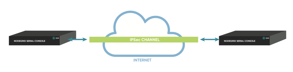
Host to Host communication means that 2 nodes have a VPN tunnel open which connects them directly. The communication which is exchanged through the tunnel is limited to direct communication between them. None of the packages will be routed or forwarded. This is essentially a point to point communication between 2 nodes.
Host to Site
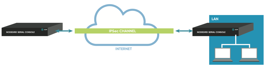
In a Host to Site communication scenario one node establishes a VPN tunnel to a 2nd node. Communication is limited on one site to the specific node and on the other side to all devices in a range of subnet which is accessible by the 2nd node
Site to Site
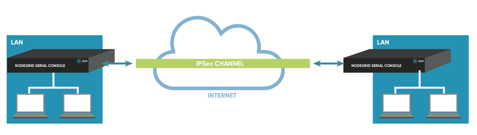
In a Site to Site communication, the tunnel is as before established between 2 nodes, communication is allowed to specific the subnet on both sides, allowing for communication between devices on either side of the connection.
Host to Multi Site
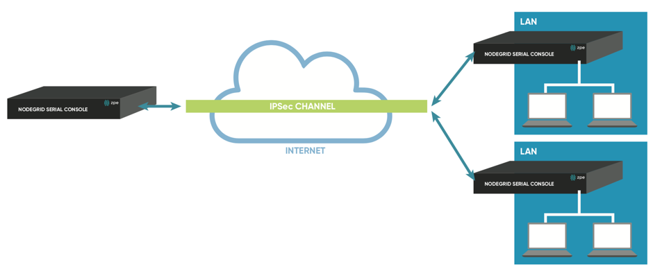
Multi-Site communication scenarios can be created by either creating individual VPN connections between hosts or by specific multi-site configurations. The later greatly improve scalability and manageability of the connection setup
As the name indicates allows a Host to multi-site communication multiple nodes to connect to the same node. A typical scenario for this would be that remote offices have a VPN connection to the main office. In this specific scenario would the communication be limited to the one node and devices on specified subnets in the remote locations.
Site to Multi Site
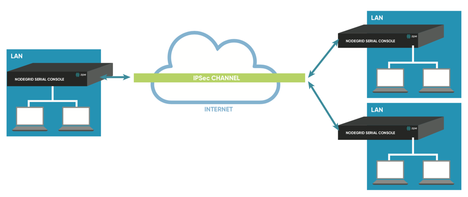
This scenario is probably the most common form for enterprise VPN setups. It is similar to the Host to multi-site option but communication is allowed to the specific subnet on either side, whereby the West node would have access to all specified subnet on any of the sites but the remote sites have only access to subnet exposed by the West node.
| Host to Host | Host to Site | Site to Site | Host to Multi-Site | Site to Multi-Site | |
|---|---|---|---|---|---|
| Pre-shared Keys | possible | possible | possible | possible | possible |
| RSA Key | Recommended | Recommended | Recommended | possible | possible |
| X.509 Certificates | Recommended | Recommended | Recommended | Recommended | Recommended |
Configuration of IPSec
This section outlines the general configuration steps which can be used to configure the desired connection.
Prepare the Nodegrid. See: How to Prepare a Nodegrid Node for IPSec
Ensure that one of the authentication methods is prepared
- How to create Pre-shared Keys for IPSec](https://desk.zoho.com/portal/zpesystemsinc/kb/articles/how-to-create-pre-shared-keys-for-ipsec)
- How to create RSA Keys for IPSec](https://desk.zoho.com/portal/zpesystemsinc/kb/articles/how-to-create-rsa-keys-for-ipsec)
- How to Create Certificates for IPSec](https://desk.zoho.com/portal/zpesystemsinc/kb/articles/how-to-create-certificates-for-ipsec)
Note: For Production environments, it is recommended to use RSA Keys or Certificate Authentication. Pre-Shared Keys are easy to set up and are a good starting point for test environments.
Create an IPSec configuration file. Configuration Examples can be found here:
Pre-Shared Keys
RSA Keys
Certificates
Distribute and exchange configuration files and Keys as required to all nodes
Test the connection
For more detailed instruction on how t use IPSec with the Nodegrid solution, visit our Knowledge Base.
Authentication
Authentication is the process of validating who you are or who you claim to be, which is usually done using credentials. Credentials take most often the form of a username and password.
Authorization is the essential security part, that complements authentication. Once you are authenticated using your credentials, authorization determines what you have access to, e.g. certain directories, power or serial devices, etc.
Nodegrid has a built-in admin user account named 'admin' with full access and rights to set all configurable aspects of the unit, network, security, authentication, authorization, devices to be managed, including other users. This special user account, 'admin' cannot be deleted and it has the default password 'admin'.
Note: For security reasons, administrators are strongly advised to change the default password during the first login by using the Change Password option on the pull-down menu under your username in the top right corner of the WebUI.
The Nodegrid platform fully the supports Authentication of local users and groups as well as external users and groups. External authentication of users and groups can be done through LDAP/AD, Tacacs+, Radius and Kerberos.
All users have access to all enabled managed devices by default. Fine Grain Authorisation can be enabled by selecting the option Device access enforced via user group authorization under Services.
Based on the groups they are assigned to, these users have limited access to Nodegrid Web portal management attributes. Privileges of users can be modified by setting profile and access rights in an authorization group. A user who belongs to the group Admin will have the same administrative privileges as the admin user. Each user must have a specific user account on Nodegrid or on an external authentication server. A user can be assigned to one or more authorization groups.
Local Accounts
New local users can be added, deleted, changed and locked under Local Accounts in Security. Administrators can force passwords to be changed upon next login and set expiration dates for the user accounts. Regardless of activation options, users can change their own passwords at any time. This feature lists all users and their respective information.
- user name and password
- hash format password (optional)
- account expiration (optional)
- groups, the user is part of
Manage Local Users
The Management of Local users can be archived under Security::Local Accounts. The following options are available
Add- New users can be addedEdit- Existing user settings can be changedDelete- Existing users can be removedLock- Existing users can be locked, this will prevent users from login in, without removing the accountUnlock- Existing locked users accounts can be unlocked
Add Local Users
Navigate to
Security::Local Accounts, all local users are displayedClick on
Addto display the Local User Information screenEnter a new user name and password
- if the password is in a hash format tick the
Hash Format Passwordcheckbox, see Hash Format Password below
- if the password is in a hash format tick the
Optionally,
- enter Account Expiration Date
- check the Require password change at login time checkbox
To add the user to an available user group, choose the group name from the box on the left and then click
Add. To remove a user group from the box, select it and clickRemoveClick
Save.
Hash Format Password
If you are an admin and prefer to not use plain password, using instead a hash format password, you can do so using this feature. This may be of special interest in using scripts, to avoids scripts containing or displaying actual passwords of the users.
It should be noticed, however, that this requires the hash password to be generated separately beforehand, using a hash password generator of your preference. Examples of popular hash generators in Linux are OpenSSL, chpasswd, mkpasswd, using MD5, SHA256, SHA512, etc..
The Nodegrid can also be used for this purpose, its own OpenSSL implementation. Example using Nodegrid's OpenSSL version
root@nodegrid:~# openssl passwd -1 -salt mysall
Password:
$1$mysall$YBFr9On0wjde5be32mC1g1
Password Rules
All local user accounts are subject to password rules. These can be adjusted under Security::Password Rules, the administrator can set values for password complexity as well as password expiration, as a set of minimum days, maximum days and warning days.
The following settings can be adjusted
| Setting | Value | Description |
|---|---|---|
| Check Password Complexity | True False | Enables or Disables, Password complexity rules. The default value is disabled |
| Password Complexity - Minimum Number of Digits | Number | Minimum amount of digits which need to be included in the password. Default value: 0 |
| Password Complexity - Minimum Number of Upper Case Characters | Number | Minimum amount of upper cases which need to be included in the password. Default value: 0 |
| Password Complexity - Minimum Number of Special Characters | Number | minimum amount of special characters which need to be included in the password. Default value: 0 |
| Password Complexity - Minimum Size | Number | minimum amount of characters included in the password. Default value: 8 |
| Password Complexity - Number of Passwords to Store in History | Number | Amount of password stored in the password history. Preventing the reuse of passwords for this amount. Default value: 1 |
| Password Expiration - Min Days | Number | Amount of days the password has to be valid for before it can be changed. Default value: 0 |
| Password Expiration - Max Days | Number | Maximum amount of days a password can be valid for before it has to be changed. Default value: 99999 |
| Password Expiration - Warning Days | Number | Amount of days, users will be notified before their password expires. Default value: 7 |
Groups
Nodegrid uses user groups to combine multiple local and remote users into a single local group, which is then used to assign system-wide administrative roles/permissions like user permission and administrative permissions. Further, are groups used to grant access permissions to specific target devices. User Groups which are authenticated against external authentication provider are mapped to local groups, this will assign the remote groups the permissions of the assigned local group.
Should a user be a member of multiple groups then the combined access rights will take effect.
Administrators can add and delete groups, as well as change their permissions. When you log in to the Nodegrid for the first time, you will see two groups in the default configuration, Admin and Users, which can not be deleted.
Manage Groups
The Nodegrid platform contains two default groups with default permissions. The admin grants the admin user full system and target access. The user group grants all members full access to all targets if Fine Grain Authorisation is disabled (default). When Fine Grain Authorisation is enabled then the user group members have no access to any target device by default.
Administrators can create, edit and delete groups under Security :: Authorization
Create a User Group
- Go to
Security::Authorizationto display all groups - Click
Addto enter the new group name and thenSave
At this point, the group has been created to change its properties and permissions click on the group name.
Add local users to a group
- Go to
Security::Authorizationto display all groups - Click on the name of the group you want to add members to
- Click on
Members. This shows a list of members already in the group - Click on
Addto show a list of local users that can be added in the left box. - Select the user and click on
Addto move the selected user to this group, in the right box. - Conversely, click on the
Remove, to remove a selected user in this group and place it back to the local user's box.
Assign system permissions and settings to a group
- Go to
Security::Authorizationto display all groups - Click on the name of the group you want to add members to
- Click on
Profile
A user group can be assigned multiple additional system permissions. All groups have by default the user permission, granting them access to the Access table. Which will allow them to connect to target devices based on the specific target permissions.
The following system permissions can be assigned.
Note: Multiple permissions can be assigned to the same group.
| Permission | Description |
|---|---|
| Track System Information | Grants access to tracking information. See section Tracking |
| Terminate Sessions | Grants the permission to terminal user and device sessions |
| Software Upgrade and Reboot System | Grants Permission to perform system upgrades and reboots |
| Configure System | Grants administrative rights to change the system configuration |
| Configure User Account | Grants permissions to change the Authorisation setting. |
| Apply & Save Settings | Grants permissions to save settings |
| Shell Access | Grants access to the system shell |
The following settings can be configured
| Setting | Value | Description |
|---|---|---|
| Permissions | Track System Information Terminate Sessions Software Upgrade and Reboot System Configure System Configure User Account Apply & Save Settings Shell Access | System Permissions |
| Restrict Configure System Permission to Read Only | True False | The granted system settings are visible but cannot be changed |
| Menu-driven access to devices | True False | The members of the group will be presented with a target menu when ssh connection directly to the Nodegrid is established. |
| Custom Session Timeout | True False | Enable a custom session time |
| Timeout [seconds] | Number | Session timeout in seconds |
| Email Events to | Email Address | list of email address to which events will be send |
Assign external groups
External groups need to be assigned to a local group. This will ensure that the remote group gets the correct permissions assigned. To assign an external group, follow the below steps
Note: This step is required for LDAP, AD, and Kerberos groups. Radius and Tacacs authentication provider offer other methods to link external groups/users to local groups.
- Go to
Security::Authorizationto display all groups - Click on the name of the group you want to add members to
- Click on
Remote Groups - List the external group names separated by a comma, which are to be assigned to the local group
- Click on
Save
Assign device permissions
In case Fine Grain Authorisation is enabled the permissions to access specific devices need to be assigned to groups. This is done by adding specific devices to a group and to set the appropriate access rights to the target. Multiple devices can be added at the same time and the access permissions can be set together.
Note: access permissions to control power outlets are granted through the
Outletspermissions and not throughDevices
Access permissions can be added ,deleted and edited for each group as necessary
- Go to
Security::Authorizationto display all groups - Click on the name of the group you want to add members to
- Click on
Devices - Click on
Add - To move managed devices from the available device list on the left to the list of authorized devices on the right, double click on the name or select the device and then click Add.
- Devices can be removed from the box on the right by double-clicking on the device or by clicking on the delete button after selecting the device to be removed
- Select desired device permissions
- click
Save
The following access permissions can be assigned
| Permission | Value | Description |
|---|---|---|
| Session | Read-Write Read-Only No-Access | Permission to access serial or ssh sessions (Console) |
| Power | Power Controll Power Status No Access | Power Control permissions through IPMI |
| Door | Door Control Door Status No Access | Door Control permissions |
| MKS | True False | Acces to MKS sessions |
| Reset Device | True False | Permission to reset a device session |
| KVM | True False | Access to KVM sessions |
| SP Console | True False | Access to IPMI console sessions (Serial over Lan) |
| Virtual Media | True False | Access to establish a Virtual Media session to an IPMI device |
| Access Log Audit | True False | Access to read the access log of an IPMI device |
| Access Log Clear | True False | Permission to clear the access log of an IPMI device |
| Event Log Audit | True False | Permission to read the device-specific event log |
| Event Log Clear | True False | Permission to clear the device-specific Event Log |
| Monitoring | True False | Permission to access monitoring features |
| Sensors Data | True False | Permission to read sensor data |
| Custom Commands | True False | Permission to execute custom commands |
Assign power outlet permissions
Access permissions for power outlets from Rack PDUs are controlled individually as the power to turn on or off a device can have severe consequences to the running of a data center or remote location. The assignment of permissions is analogous to device's access permissions.
Go to
Security::Authorizationto display all groupsClick on the name of the group you want to add members to
Click on
OutletsClick on
AddTo move managed devices from the available device list on the left to the list of authorized devices on the right, double click on the name or select the device and then click Add.
Devices can be removed from the box on the right by double-clicking on the device or by clicking on the delete button after selecting the device to be removed
Select desired device permissions
- Power Control - Permission to turn on or off an outlet
- Power Status - Permission to see the current outlet status
- No Access
click
Save
External Authentication Provider
Nodegrid provides an easy and simple way to enable external authentication on the platform. It can be set up to authenticate users with:
- Active Directory and LDAP (Lightweight Directory Access Protocol),
- TACACS+ (Terminal Access Controller Access-Control System Plus),
- RADIUS (Remote Authentication Dial-In User Service)
- Kerberos (based on tickets to prove identity)
In order to allow external users access to the Nodegrid platform the following steps need to be performed independently of the specific authentication provider
- An Internal group needs to be created
- Permission needs to be assigned to the group
- External Authentication Provider needs to be added, see below
- External groups need to be mapped to an internal group
Authentication providers can be added, deleted, modified in the Security :: Authentication section. The section will display all currently configured authentication providers and allows the creation, deletion, modification, and order of the authentication providers.
The order of the authentication providers determents which one will be used first to authenticate the user. Should the authentication then fail the user access might be rejected or the next authentication provider might be tried. The authentication provider setting Fallback if denied access control this. When enabled then the next provider will be used. If disabled the user access will be granted or denied based on the result.
Note: Should a provider not be available to authenticate users at any given time then the provider will be skipped and the next provider will be used.
All users accessing the Nodegrid need to be a member of a group. If a user can not be identified as being a group member then a default group will be used. By default, this is the user group. The group which will be used can be adjusted using the Default Group option
The following section outlines how the different external authentication providers are added and configured.
LDAP and Active Directory
The LDAP protocol is an open standard and there is a large variety of implementations, all similar but bearing slight variations. LDAP examples shown are based on OpenLDAP implementation.
Microsoft’s Active Directory is one of the largest and widely used implementations of LDAP, it allows implementation of very complex authentication provider structure reflecting the internal organization of companies.
Provide the following information to set up an LDAP or Active Directory authentication server.
| Field | Values | Description |
|---|---|---|
| Status | True False | Default Value is Enabled. This means the provider will be used to authenticate users |
| Fallback if denied access | Enabled or Disabled | Default is Disabled. It is recommended to Enable this feature in case the provider is not available. |
| Remote Server | FQDN or IP of LDAP server or domain | Nodegrid supports resolution of Active Directory Servers through DNS requests. This means that either specific Active Directory Servers can be specified or a valid Active Directory Domain. In case of the later, the system will contact the closest Server based on the DNS results. |
| Base | Base DN | This field can contain the Root DN or a sublevel DN. This DN marks the highest point which will be used to search for users or groups |
| Secure | On, Off or Start_TLS | Default is off, all traffic between the Nodegrid and the LDAP server will be sent unencrypted. On is recommended. (This feature needs to be supported by the Server) |
| Global Catalog Server | True False | When enabled that the provider will use an Active Directory Global Catalog Server |
| Database Username | Search User Name | Full Qualified username, which can be used to search through the directory. Only required if the LDAP server requires authentication for browsing of the directory |
| Database Password and Confirm Password | Password for the search user | Only required if the LDAP server requires authentication for browsing of the directory |
| Login Attribute | Field identifies the username | attribute field which contains the username. For Active Directory this is sAMAccountName by default. |
| Group Attribute | Field identifies the group names | Attribute filed which contains the group identifier. For Active Directory this is memberOf by default |
| Search Filter | Search Filter following the LDAP implementation |
Example configuration for OpenLDAP server
| Field | Value |
|---|---|
| Status | True |
| Fallback if denied access | True |
| Remote Sever | 192.168.1.1 |
| Base | dc=zpe,dc=net |
| Secure | Off |
| Global Catalog Server | False |
| Database Username | cn=admin,dc=zpe,dc=net |
| Login Attribute | cn |
| Group Attribute | memberUID |
Example configuration for Active Directory server
| Field | Value |
|---|---|
| Status | True |
| Fallback if denied access | True |
| Remote Sever | 192.168.1.1 |
| Base | dc=zpesystems,dc=com |
| Secure | Start TLS |
| Global Catalog Server | True |
| Database Username | cn=Administrator,cn=Users,dc=zpesystems,dc=com |
| Login Attribute | sAMAccountName |
| Group Attribute | memberOf |
More information on how to setup LDAP and Active Directory can be found under How to Configure Active Directory or LDAP Authentication Provider
TACACS +
Terminal Access Controller Access-Control System Plus (TACACS+) is a protocol developed by Cisco and released as an open standard beginning in 1993. Although derived from TACACS, TACACS+ is a separate protocol that handles authentication, authorization, and accounting (AAA) services. TACACS+ and other flexible AAA protocols have largely replaced their predecessors.
| Field | Values | Description |
|---|---|---|
| Status | True False | Default Value is Enabled. This means the provider will be used to authenticate users |
| Fallback if denied access | Enabled or Disabled | Default is Disabled. It is recommended to Enable this feature in case the provider is not available. |
| Remote Server | IP address | |
| Accounting Server | IP address | |
| TACACS+ Port | TCP Port | Default port 49 |
| Service | ppp shell raccess | Authentication service used by TACACS. The default value is raccess |
| Secret/Confirm Secret | Secret | |
| Timeout | Number | Communication timeout in seconds. Default value: 2 |
| Retries | Number | Amount of retries before connection fails |
| TACACS+ Version | V0 V1 V0_V1 V1_V0 | TACACS version to be used. The default value is V1 |
| Enable User-Level attribute of Shell and raccess services association to local authorization group | True False | |
| User Level 1 - 10 | Nodegrid group name |
RADIUS
RADIUS is a client/server protocol that runs in the application layer and can use either TCP or UDP as transport. Operating on port 1812, it provides centralized Authentication, Authorization, and Accounting (AAA) management for users.
The Nodegrid Platform allows multiple methods to assign Radius users to Nodegrid groups. the following options exist:
- Radius Service Types can be assigned to Nodegrid groups using the settings in the Authentication provider
- On the Radius server can the attribute
Framed-Filter-IDbe used to assign a user to a Nodegrid group Example:Framed-Filter-ID = “group_name=<ng-groupname>[,<ng-groupname1>];”
| Field | Values | Description |
|---|---|---|
| Status | True False | The default Value is Enabled. This means the provider will be used to authenticate users |
| Fallback if denied access | Enabled or Disabled | Default is Disabled. It is recommended to Enable this feature in case the provider is not available. |
| Remote Server | IP address | |
| Accounting Server | IP Address | |
| Secret / Confirm Secret | Secret | |
| Timeout | Number | Communication timeout in seconds. The default value: 2 |
| Retries | Number | Amount of retries before connection fails |
| Enable ServiceType attribute association to local authorization group | True False | Allows the assignment of Radius Service Types to Nodegrid local groups |
| Service Type Login | Nodegrid group name | |
| Service Type Framed | Nodegrid group name | |
| Service Type Callback Login | Nodegrid group name | |
| Service Type Callback Framed | Nodegrid group name | |
| Service Type Outbound | Nodegrid group name | |
| Service Type Administrative | Nodegrid group name |
Kerberos
Kerberos is a computer network authentication protocol that uses tickets to allow nodes communicating over a non-secure network to prove their identity to one another in a secure manner. Designed primarily as a client–server model, it provides mutual authentication. Both the user and the server verify each other's identity. It builds on symmetric key cryptography and requires a trusted third party, and optionally may use public-key cryptography. It uses UDP port 88 by default.
| Field | Values | Comment |
|---|---|---|
| Status | True False | Default Value is Enabled. This means the provider will be used to authenticate users |
| Fallback if denied access | Enabled or Disabled | Default is Disabled. It is recommended to Enable this feature in case the provider is not available. |
| Remote Server | IP address | |
| Realm Domain Name | Kerberos realm name | |
| Domain Name | domain name |
Security
Firewall
Nodegrid acts as a Firewall when configured to do so by an administrator. There are six built-in default chains, three for IPv4 and three for IPv6. These accept Output, Input and Forward packets. Additional User chains can be created and deleted if required. For each chain, the default policy can be set. The default policy is set to Accept packages.
Default chains cannot be deleted.
Rules can be created for each chain, by clicking on the chain name. This will list all existing rules belonging to the chain. Rules can be created, deleted and modified. The following settings exist for rules. For more details review the iptables documentation.
| Setting | Values | Description |
|---|---|---|
| Target | ACCEPT DROP REJECT LOG RETURN | |
| Source IP/Mask | IP address and mask | |
| Reverse match for source IP/mask | TRUE FALSE | |
| Destination IP/Mask | IP address and mask | |
| Reverse match for destination IP/mask | TRUE FALSE | |
| Input Interface | Any Available interfaces | one value of the list can be selected |
| Reverse match for input interface | TRUE FALSE | |
| Output Interface | Any Available interfaces | one value of the list can be selected |
| Reverse match for output interface | TRUE FALSE | |
| Enable State Match | NEW ESTABLISHED RELATED INVALID | one or multiple States can be selected |
| Reverse state match | TRUE FALSE | |
| Fragments | All packets and fragments Unfragmented packets and 1st packets 2nd and further packets | one value of the list can be selected |
| Reject With | Network Unreachable Host Unreachable Port Unreachable Protocol Unreachable Network Prohibited Host Prohibited Administratively Prohibited TCP Reset | |
| Protocol | Numeric TCP UDP ICMP | |
| Protocol - Numeric - Protocol Number | Protocol Number | |
| Protocol - TCP - Source Port | Port Number | |
| Protocol - TCP - Destination Port | Port Number | |
| Protocol - TCP - TCP Flag SYN | Any Set Unset | |
| Protocol - TCP - TCP Flag ACK | Any Set Unset | |
| Protocol - TCP - TCP Flag FIN | Any Set Unset | |
| Protocol - TCP - TCP Flag RST | Any Set Unset | |
| Protocol - TCP - TCP Flag URG | Any Set Unset | |
| Protocol - TCP - TCP Flag PSH | Any Set Unset | |
| Protocol - TCP - Reverse match for TCP flags | TRUE FALSE | |
| Protocol - UDP - Source Port | Port Number | |
| Protocol - UDP - Destination Port | Port Number | |
| Protocol - ICMP - ICMP Type | Any Echo Reply Destination Unreachable Network Unreachable Host Unreachable Protocol Unreachable Port Unreachable Fragmentation Needed Source Route Failed Network Unknown Host Unknown Network Prohibited TOS Network Unreachable TOS Host Unreachable Communication Prohibited Host Precedence Violation Precedence Cutoff Source Quench Redirect Network Redirect Host Redirect TOS Network Redirect TOS Host Redirect Echo Request Router Advertisement Router Solicitation Time Exceeded TTL Zero During Transit TTL Zero During Reassembly Parameter Problem Bad IP Header Required Option Missing Timestamp Request Timestamp Reply Address Mask Request Address Mask Reply | |
| Protocol - ICMP - Reverse match for ICMP type | TRUE FALSE | |
| Reverse match for protocol | TRUE FALSE | |
| Reverse match for source port | TRUE FALSE | |
| Reverse match for destination port | TRUE FALSE | |
| Log Level | Debug Info Notice Warning Error Critical Alert Emergency | |
| Log Prefix | Log Prefix String | |
| Log TCP Sequence Numbers | TRUE FALSE | |
| Log Options From The TCP Packet Header | TRUE FALSE | |
| Log Options From The IP Packet Header | TRUE FALSE |
Services
The Services page allows defining the Active Services running on the system as well as general service settings for Managed Devices, Intrusion Prevention, SSH settings to the systems itself, Web Service settings and Cryptographic Protocols for the Web Service.
This allows configuring the security level of the system. For instance, can unsecured protocols like Telnet or HTTP be disabled, or the SSH version which is allowed to access the system.
Active Services
The Active Services page allows the control which Services should be enabled in the system and which network ports they should be using.
The following settings are available
| Setting | Value | Description |
|---|---|---|
| Enable detection of USB devices | TRUE FALSE | Enabled by Default |
| Enable RPC | TRUE FALSE | Required for NFS share access |
| Enable FTP Service | TRUE FALSE | |
| Enable SNMP Service | TRUE FALSE | Enabled by Default |
| Enable Telnet Service to Nodegrid | TRUE FALSE | |
| Telnet TCP Port | Port number | Default value: 23 |
| Enable Telnet Service to Managed Devices | TRUE FALSE | |
| Enable ICMP echo reply | TRUE FALSE | Enabled by Default |
| Enable USB over IP | TRUE FALSE | |
| Enable Virtualization Services | TRUE FALSE | Needs to be Enabled in order to run NFV's or Docker apps. Both features require licenses |
| Cloud TCP Port | Port Number | Default value: 9966 |
| Enable Automatic Cloud Enrollment | TRUE FALSE | |
| Search Engine TCP Port | Port Number | Default Value: 9300 |
| Enable Search Engine High Level Cipher Suite | TRUE FALSE | |
| Enable VM Serial access | TRUE FALSE | Enabled by Default |
| VM Serial Port | Port Number | Default Value: 9977 |
| vMotion timeout [seconds] | Number in seconds | Default Value: 300 |
| Enable Zero Touch Provisioning | TRUE FALSE | Enabled by Default |
| Enable PXE (Preboot eXecution Environment) | TRUE FALSE | Enabled by Default |
Managed Devices
The Managed Devices section allows controlling of general aspects and services controlling managed devices. The following settings are available.
| Setting | Value | Description |
|---|---|---|
| Device access enforced via user group authorization | TRUE FALSE | When this feature is enabled, users will only have access to devices listed under the authorization groups that the user belongs. If this feature is not enabled, all enrolled devices in the Nodegrid will be available to the user and the user will be able to access them without restriction. |
| Enable Autodiscovery | TRUE FALSE | This feature allows the Auto Discovery of managed devices on the network. |
| DHCP lease controlled by autodiscovery rules | TRUE FALSE | If this feature is enabled then the DHCP server will only server leases to devices which have been discovered through the Auto Discovery process. This feature is only available when Enable AutoDiscovery is enabled. |
Intrusion Prevention
The Intrusion Prevention section allows the configuration of mechanisms which can prevent unauthorized access to a system, like Fail 2 Ban and Rescue Mode. The following settings are available.
| Setting | Value | Description |
|---|---|---|
| Block host with multiple authentication fails | TRUE FALSE | |
| Period Host will stay blocked (min) | Number in min | Amount of time the system will not be reachable on the network. Default value:10 |
| Timeframe to monitor authentication fails (min) | Number in min | Amount of time during which failed authentication attempts are counted and before the counter gets reset. Default value:10 |
| Number of authentication fails to block host | Number | Amount of failed authentication attempts during Number of authentication fails to block host before the host will be blocked. Default value:5 |
| Rescue Mode requires authentication | TRUE FALSE | After the feature is enabled the Rescue Mode will require authentication through a local user account, like root. |
SSH
The SSH section allows configuration of the SSH service controlling access to the Nodegrid system. The following settings are available.
| Setting | Value | Description |
|---|---|---|
| SSH allow root access | TRUE FALSE | Allows root access through SSH, Enabled by default. |
| SSH TCP Port | Port Number | Devalt value: 22 |
| SSH Ciphers | allowed list of ciphers | Default value: blank, which allows all ciphers which are supported by Nodegrid |
| SSH MACs | allowed list of MAC addresses | Default value: blank, which allows all systems to access the Nodegrid via ssh |
| SSH KexAlgorithms | an allowed list of key exchange algorithms | Default value: blank |
Web Service
The Web Service section allows the configuration of the web server. The following settings are available.
| Setting | Value | Description |
|---|---|---|
| Enable HTTP access | TRUE FALSE | Default value: Enabled |
| HTTP Port | Port Number | Default value: 80 |
| Enable HTTPS access | TRUE FALSE | Default value: Enabled |
| HTTPS Port | Port Number | Default value: 443 |
| Redirect HTTP to HTTPS | TRUE FALSE | Default value: Enabled |
Cryptographic Protocols
The Cryptographic Protocols allow configuration of ciphers which are supported to access the web server. The following settings are available.
| Setting | Value | Description |
|---|---|---|
| TLSv1.2 | TRUE FALSE | Default value: Enabled |
| TLSv1.1 | TRUE FALSE | Default value: Enabled |
| TLSv1 | TRUE FALSE | Default value: Disabled |
| Cipher Suite Level | High Medium Low Custom | Default value: Medium |
Cloud
Cloud is a Nodegrid feature that establishes a secure and resilient connection among other Nodegrid platforms so that when Cloud Clustering is enabled, multiple Nodegrid systems can easily manage and access all managed devices from other nodes. Nodegrid makes cloud access management even easier with cloud asset search. By logging into any Nodegrid node users can search the entire Nodegrid-managed enterprise network and cloud with a single interface.
This allows for vertical and horizontal scalability.
Peers Overview
The Peers page lists all Nodegrid units that are enrolled in the cloud.
The table shows the name of each Nodegrid, their IP Addresses, type, and status of communication with other peers.
Peers can be removed by selecting entries and then clicking on the Remove button.
If the Nodegrid is the coordinator, it cannot be removed from the table.
Cloud Settings
In this section, the Cloud feature and the additional services Perr Management and License Pool can be enabled and configured.
Note: The Cloud feature requires a software license for each node in the cloud.
Enable Cloud
The Cloud feature can be enabled by checking the Enable Cloud checkbox. Each Cloud requires to have one Coordinator which coordinates and controls the enrollment of peer systems.
The first unit the cloud needs to be set as Type Coordinator. all other units can then be set to type Peer. The role of the Coordinator can later be changed to another system by selecting the Type of Coordinator on a peer. The change will then automatically propagated through the system.
If the Nodegrid is the coordinator, make sure the Allow Enrollment checkbox is checked, and provide a Cloud Name and Pre-Shared Key so that peers can be enrolled to the Cloud.
Please note that the Cloud Name and the Pre-Shared Key will be used in the Peer’s settings.
If the Nodegrid is the Peer, then enter the Coordinator’s Cloud Name, Coordinators's Address, and the Pre-Shared Key.
Check the Enable Clustering checkbox for allowing other Nodegrid systems to manage, access, and search all managed devices from other nodes.
Note: The Coordinator is only required for the enrollment of the peers. Once all Nodegrid systems were enrolled into the Cloud, the Coordinator can be set as Peers to prevent the enrollment of other units.
Automatic Enrollment
The Automatic Enrollment features allow administrators to automatically add new Nodegrid systems which become available to an existing cloud. The feature is enabled by default for Peers to be detected. The setting Pre-Shared Key need to be the same on the Coordinator as well as on the Peers. It is set by default to nodegrid-key. The value Interval [seconds] only applies to coordinators and regulates how often invitations are sent to potential peers based on the define network list.
After the Coordinator is enabled and configured, the admin user can add a range of IPs where other Nodegrid systems are on the network. To add network ranges for the discovery process add them to the Automatic Enrollment Range page under Cloud Settings.
Note: It is recommended to only add IP's to the Automatic Enrollment Range which are potentially Nodegrid units, as the system will send continually invitations to all IP's until a Nodegrid unit was found on a specific IP and it was added to the Cloud.
This way, the Coordinator will communicate with any Nodegrid system on those ranges and add them to the Cloud, thus eliminating the need to go to each of the Nodegrid nodes and set them as peers.
License Pool
The License Pool features allow for central management of all software licenses within a cloud. For this at least one unit needs to be set up as a License Pool Server, all other units are set up as License Pool Clients, which is the default setting.
License Pool Clients will automatically request required licenses from the License Pool Server. Licenses Pool Server will check the availability of licenses and assign the requested licenses if they are available. The Client will renew the licenses dependent on the servers Renew Time [days]. In case a client becomes unavailable for an extended period of time and exceed the servers Lease Time [days], then the licenses will become invalid on the client and return to the pool.
The currently leased licenses can be viewed on the License Pool Server in the Licenses section.
Peer Management
The Peer Management feature enables a function to centrally upgrade the firmware of Nodegrid units in the cloud. To enable the feature select Enable Peer Management.
The cloud Management page allows then to start the software upgrade process for remote Nodegrid units from a central location. The firmware which will be applied to the units needs to be hosted on a central location which is available through a URL.
Note: The URL should include the remote server’s IP or hostname, file path, and the ISO file. For example:
ftp://192.168.2.200/nodegrid/Nodegrid_Platform_v3.1.0_20160127.iso
The page lists all Nodegrid systems in the Cloud. Select desired nodes that have the Management Status as Idle. If the status shows disabled, it means that the Nodegrid has Peer Management feature disabled. Once the selection is done, click on the Software Upgrade button. Select Remote Server and enter URL, Username, and Password.
The option Format partitions before upgrade will reparation the Nodegrid units hard drive before performing the firmware upgrade.
If downgrading the software, you have the option to Restore configuration saved on version upgrade or Apply factory default configuration.
Auditing Settings
The auditing feature allows events which have been created to be sent to four different destinations: Email, File, SNMP Trap, and Syslog. It also allows data logging and events logging to be stored locally, remotely via NFS or sent to a Syslog server.
Data Logging
The Data logging feature allows capturing the data stream going to and coming from target devices as well as from the Nodegrid system. General settings for the data logging feature are available under Auditing :: Settings. The following settings are available.
| Setting | Values | Description |
|---|---|---|
| Enable File Destination | TRUE FALSE | When the feature is enabled all Data Logs are stored to the defined File location under Auditing Destinations. Default Value: Enabled |
| Enable Syslog Destination | TRUE FALSE | When the feature is enabled all Data Logs are sent to the defined Syslog location under Auditing Destinations.Default Value: Disabled |
| Add Timestamp on every line logged | TRUE FALSE | When this feature is enabled, a timestamp will be added to each data log line |
| Timestamp Format | UTC Local Time | Defines the timestamp timezone, which will be used. Default value: UTC |
Events
The Nodegrid system automatically creates events based on its and device settings. All events get stored to the local file system by default. This behavior can be adjusted under Auditing :: Events. The administrator can configure to which destination events get logged and which event categories get logged.
The system supports 4 event categories which can be individually controlled:
- Systems Events
- AAA Events
- Device Events
- Logging Events
Note: Under
Tracking :: Event Listare all events listed and the category they belong to.
Each of these event categories can be configured to send the events to any of the 4 event destinations or to none. Event Destinations are:
- File - This can be local File storage or NFS file storage
- Syslog - This can be local Syslog or remote
- SNMP Trap
Destinations
File
Data logs are written by default to files which are maintained locally. The file destination and archive settings can be set under Auditing :: Destinations :: File
Note: NFS requires RPC service to be enabled in Security :: Services
The following options are available.
| Setting | Values | Description |
|---|---|---|
| Destination | loacal NFS | |
| NFS - NFS Server | IP address of NFS Server | |
| NFS - NFS Path | Path to the NFS root directory | Each unit should have its own root directory. |
| File Size [Kbytes] | File size in Kbytes | File size at which the file will be rotated. Valid values are between 0 (disabled) and 2048 Kb. Default value: 1024. |
| Number of Archives | Number | Number of archive files which should be kept before they will be discarded. Default value: 10 max value: 99 |
| (NFS) Archive by Time [HH:MM] | Time in format HH:MM | Time at which the file archive will be rotated. Default value: blank |
Syslog
The Syslog destination can be used to store data logs and event notifications. The system supports a local Syslog destination or a remote IPv4 and IPv6 destination.
The following option is available.
| Setting | Values | Description |
|---|---|---|
| System Console | TRUE FALSE | Syslog events will be displayed on the Nodegrid system console port sessions. By default, this option is enabled |
| Admin Session | TRUE FALSE | Syslog events will be displayed and any admin session which is open to the Nodegrid system. By default this option is disabled. |
| IPv4 Remote Server | IP address | One or multiple IP addresses can be provided. Addresses need to be separated by a comma. |
| IPv4 Address or Hostname | TRUE FALSE | By default is disabled |
| IPv6 Remote Server | IP address | One or multiple IP addresses can be provided. Addresses need to be separated by a comma. |
| IPv6 Address or Hostname | TRUE FALSE | By default is disabled |
| Event Facility | Log Local 0 Log Local 1 Log Local 2 Log Local 3 Log Local 4 Log Local 5 | Defines the Syslog logging facility for Events |
| Data Logging Facility | Log Local 0 Log Local 1 Log Local 2 Log Local 3 Log Local 4 Log Local 5 | Defines the Syslog logging facility for data logs |
SNMP Trap
Any triggered event can be sent via an SNMP trap to an existing NMS system. The Nodegrid system supports SNMP v2 and 3 for traps. The MIB files for the Nodegrid system are available together with the firmware files.
Note: SNMP3 INFORM messages are currently not supported.
The following options are available.
| Setting | Value | Description |
|---|---|---|
| SNMP Engine ID | none | Displayes the systems Engine ID |
| Server | IPv4 or IPv6 IP address | |
| Transport Protocol | UDP-IPv4 TCP-IPv4 UDP-IPv6 TCP-IPv6 | protocol used to send the traps. Default is UDP-IPv4. |
| Port | TCP port | default value is 161 |
| Trap Version | Version 2c Version 3 | SNMP version to be used |
| Version 2c - Community | community name | |
| Version 3 - User Name | user name | |
| Version 3 -Security Level | noAuthNoPriv authNoPriv authPriv | |
| Version 3 -Authentication Algorithm | MD5 SHA | |
| Version 3 -Authentication Password | Password | |
| Version 3 -Privacy Algorithm | DES AES | |
| Version 3 -Privacy Passphrase | Passphrase |
Email Notification
Events can be sent via Email to an email address. The following options are available.
| Setting | Value | Description |
|---|---|---|
| Server | SMTP server address | |
| Port | TCP port to be used | Default port is 25 |
| Username | Username | |
| Password | Password | |
| Confirm Password | Password | |
| Destination Email | email address | target email address to which the events will be sent to |
| Start TLS | TRUE FALSE | Should TLS be used for the communication |
Monitoring
The Monitoring feature allows Nodegrid to monitor and collect sensor data from Managed Devices which are connected to a Nodegrid sensor or support SNMP or IPMI as a protocol.
The collected data are defined and controlled through Monitoring Templates which will be assigned to a monitored device during its configuration.
Customizing a Monitoring Template
There are a number of pre-existing monitoring templates, which typically fulfill the user's requirements. Should the need arise then these templates can be customized.
All templates are text files located in subdirectories of the/etc/collectd.templates directory according to the protocol used to collect the monitoring data, either SNMP or IPMI.
/etc/collectd.templates/snmp/etc/collectd.templates/ipmi
Any new file in these directories will automatically appear in the user interface.
SNMP Template
To create a new SNMP template, log in as root to the shell. Create a copy of one existing template as a starting point for the new template.
Each SNMP template file has two types of subsections:
Data
- One entry per data point, each identified by a unique ID.
Host
- One single entry, defines SNMP parameters, the collecting interval, and which data points are to be collected.
The template file should only include data points which are of interest, all other data points can be removed from the file.
The following table explains the settings and the possible values for a data entry
| Setting | Value | Description |
|---|---|---|
| Data | Internal name of the Data point as it will be collected by the Nodegrid system. The Name should be unique. | the name should not have any spaces. Example Data "pdu_in_cur" Data "pdu_in_vol" |
| Type | temperature fanspeed humidity counter percent timeleft voltage current power apparent_power power_factor frequency | data type |
| Table | true false | reflects if the OID is part of a table or not |
| Instance | true false | If Table is true: A SNMP OID prefix that will be walked to retrieve a list of names that will be associated with the corresponding values. For example, in a PDU this could be the outlet name. If Table is false: The name [of the instance] that will be associated with the value, as a string. |
| InstancePrefix | String | Optional. A string to the prepended to the Instance, enclosed in double quotes. |
| Values | true false | If Table is true: The SNMP OID prefix that will be walked to retrieve a list of values. If Table is false: The SNMP OID used to retrieve a single value. |
| Scale | Decimal value | Optional. A decimal value to be multiplied to the value retrieved before persisting it. |
Example
    <Data "pdu_in_cur">
      Type "current"
      Table true
      Instance ".1.3.6.1.4.1.476.1.42.3.8.40.20.1.20"
      Values ".1.3.6.1.4.1.476.1.42.3.8.40.20.1.130"
      Scale 0.01
    </Data>
The host entry in an SNMP template dose only requires an adjustment in the Collect setting. The values list should contain a list of all data entries which should be collected. All listed data entries require a corresponding data entry definition.
IPMI Discovery Template
The ‘discover’ template for IPMI will automatically discover all the sensors available on an IPMI device.
The template will have only one subsection, Host, and the options of interest are:
| Setting | Value | Description |
|---|---|---|
| AuthType | none md2 md5 straight | The authentication type for the IPMI protocol. The default is to negotiate the strongest one. |
| Privilege | callback user operator admin | The privilege level for the IPMI protocol. The default is admin. |
| Sensor | Name of the Sensor to be collected | Selects sensors to collect or to ignore, depending on IgnoreSelected. May be defined multiple times, each one selecting one sensor. |
| IgnoreSelected | true false | If true, will not collect that for the sensors selected by Sensor. If false will only collect the sensors selected by Sensor. |
| Scale | “ | Optional. A decimal value to be multiplied to the value retrieved before persisting it. |
Enabling Monitoring
Monitoring is enabled on a per-device basis. The settings are part of the Managed Device settings. To enable Monitoring are the following steps required.
- Navigate to the device in the
Managed Devicesection. - Navigate on the specific device to the
Managementsection - Enable and configure the required monitoring protocol like SNMP or IPMI
- Enable Monitoring and assign the template and assign the collection interval.
Dashboard
Nodegrid provides the dashboard tool to visually see Event Details, Managed Device details and monitoring data from the system and the Managed Devices. It gives the flexibility to create several dashboards for different purposes and monitor managed devices data points such as Power Consumption, Voltage (V), Current (A), Temperature, Fan speed, and many more. It provides options to show data from a different period of times such as the last 15 minutes, the last hour, the last day, this week, this month, the last 5 years.
The Dashboard guide will provide a starting point on how to create simple and useful Dashboards which can be expanded if needed and allow users to create the dashboards which are relevant.
Note: The Dashboard feature is only available through the WebUI
Exploring Data Points
This section is not required, but it will describe how it can be verified that the collected data are stored and to learn more about the data being collected. The raw data points which are collected can be viewed by performing the steps below.
Click on
DashboardClick on
DiscoverSelect the desired Index Pattern
logstash-*contains monitored data*_date_*contains event notifications
By default, all data are displayed which were collected in the defined timeframe.
- Adjust the timeframe as needed
- Use the
Searchfield to search for a specific device or datapoint
Verify that data points where collected and inspect the available fields.
Note: As collected data is buffered before being stored, it can take a couple of collection cycles before the data can be visualized.
The following fields can be used in search expressions.
Data Point fields (logstash-* Index )
| Field | Values | Description |
|---|---|---|
| host | Device Name | The name of the device being monitored. |
| plugin | snmp ipmi nominal aggregation | Name of the collection plugin |
| plugin_instance | sum average | The instance of the plugin collecting the data, if the plugin requires it. Present iin the aggregation plugin |
| collectd_type | temperature fanspeed humidity counter percent timeleft voltage current power apparent_power power_factor frequency | Type of measurement |
| type_instance | Data Point Name | The name of the element associated with the measurement |
Device fields (logstash-* Index )
| Field | Values | Description |
|---|---|---|
| name | Device Name | The name of the device being monitored. |
| mode | enabled ondemand disabled | operational mode of the device |
| type | device type | Device type as assigned to the device under Managed Devices |
| family | ilo drac ipmi_1.5 ilmi_2.0 cimc_ucs device_console pdu | device family |
| addr_location | Address | |
| coordinates | Coordinates | |
| ip | IP address | |
| mac | MAC address | The MAC address of the device, if known. |
| alias | IP address alias | |
| groups | list of groups | The authorization groups which have granted access to the device |
| licensed | yes no | device license state |
| status | connected disconnected in-use unknown | The current status of the device |
| nodegrid | Nodegrid hostname | The hostname of the Nodegrid that controls the device |
| custom fields | Any custom field configured for the device |
Event fields (*_date_* Index )
| Field | Value | Description |
|---|---|---|
| event_id | Number | Event ID number |
| event_msg | Text | Event Message |
| host | Nodegrid hostname | hostname of the Nodegrid where the Event occurred. |
| message | Text | Full message text |
Creating a Visualization
Visualizations allow the gathered data to be displayed on a Dashboard. The Visualization includes a wide variety of different options to display and aggregate data. The following sections cover a small subset of the options available and aim to be a starting point in the creation process of custom visualizations.
Line Charts
Line Charts allow the visualization of data points along the line graph. It is one of the most common graphs used.
The following process outlines the general steps to create a line chart.
Click on
Visualize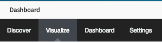
Select a Visualisation Style to be used. In this example, a
Line Chartwill be created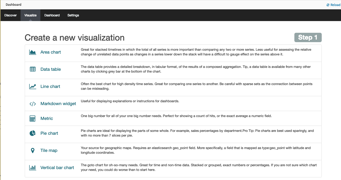
Select a search sourceby clicking on From a new search.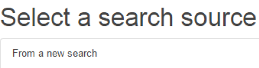
Select logstash-* as
index pattern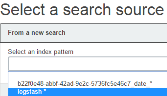
Select the data points you want to visualize by entering a search expression such as
host:”<device name>”in the search field.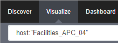
The search expression can be extended to be more selective.
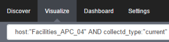
Click on the
Arrowto the left of Y-Axis to expand it.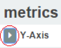
Select Average for
Aggregationand value for Field.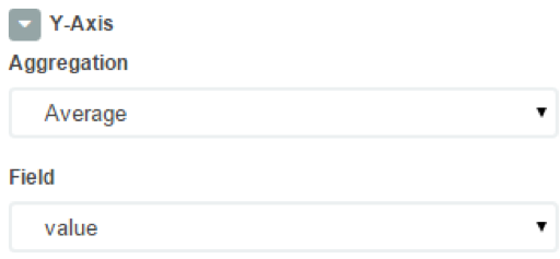
Click on X-Axis.
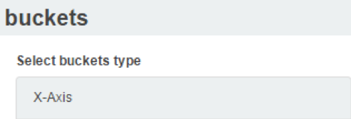
Select Date Histogram as
Aggregation. LeaveFieldandIntervalas default. If you just want your visualization to be a single-line graph, skip the next sub-steps, as the next steps will split the data point set into a multi-line graph.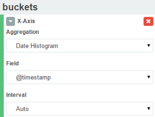
Click on
Add sub-bucketsto add multiple data points.
Click on
Split Lines.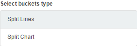
Select Filters as
Sub Aggregation.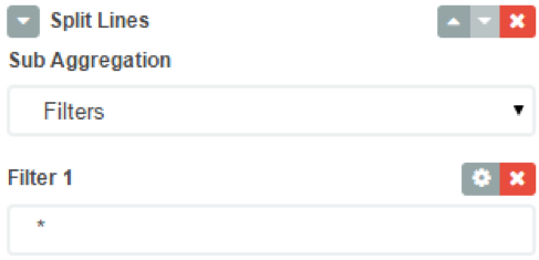
Enter a search expression to select the element you want to visualize.
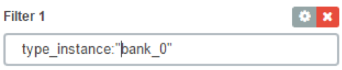
Optionally, associate a label by clicking on the
settings icon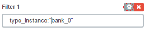
provide a label
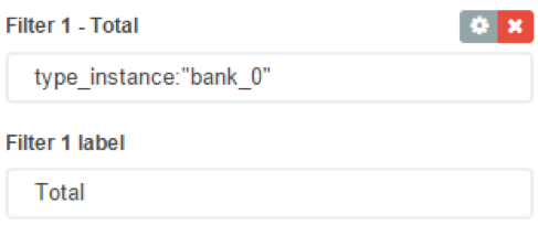
Click on
Add Filterto add another element to the visualization
- Repeat these steps to add all desirable elements
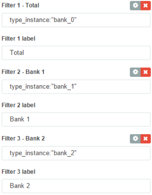
- Repeat these steps to add all desirable elements
Click on the the green arrow to refresh the graph based on the configuration provided.

The graph will reflect the configuration provided.
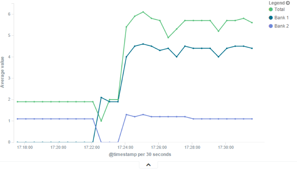
Click on the
Saveicon to save the visualization.
Provide a Title for the visualization and click on
Save.
Area Charts
The area chart, which is useful for stacking measurements for different although related entities, such as the outlets of a PDU.
Note: Review the
Line Chartsection before continuing with theArea Chart
Click on
VisualizeSelect a Visualisation Style to be used. In this example, a
Area Chartwill be created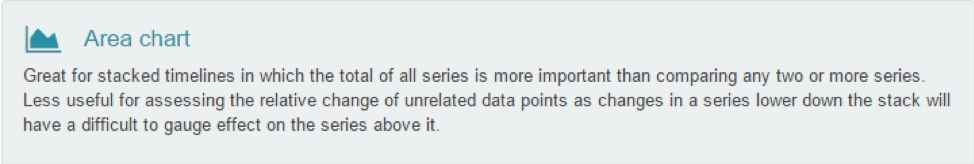
Configure the visualization options to have
Chart Modeas stacked.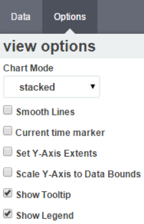
This is the appearance of such a visualization
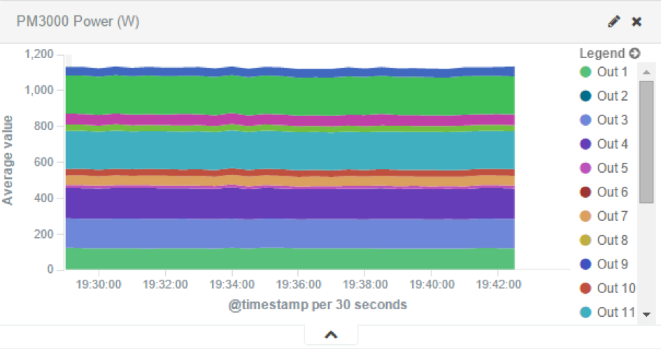
All search expressions are used to select, or limit, the data points that will be used to compose the visualization. They can be used as a filter for the whole visualization, as sub-aggregation filters, or as a filter for the whole dashboard.
These search expressions are not restricted to the data points’ fields, but they can also refer to fields associated with the device in Nodegrid, such as type, IP address, authorization groups, custom fields, and more
For example, to collect the current provided by each outlet in a selection of Rack PDUs, one with custom field “rack:abc” and another with “rack:xyz”.
To show the total sum of the current provided by outlets of each Rack PDU the following settings can be used.
- Visualization
Aggregationas Sum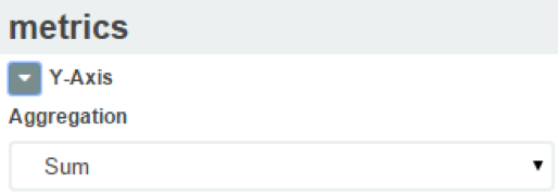
- the
bucketsinterval to match the collecting period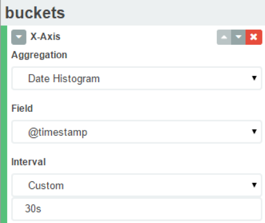
Sub-Aggregationfilters are set to custom fields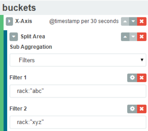
- Visualization
The resulting visualization would look like this
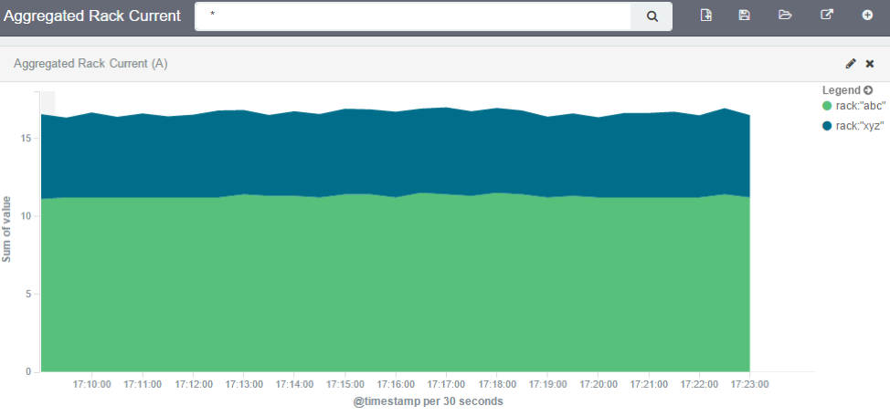
Filters can be added to display the values of only one Rack PDU by using the IP address
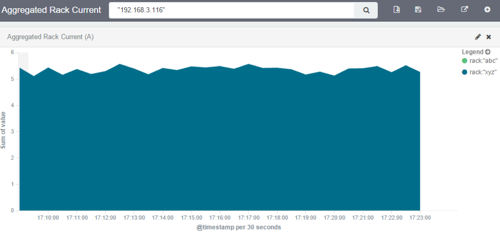
Additional filters can be used as needed, all from the same visualization.
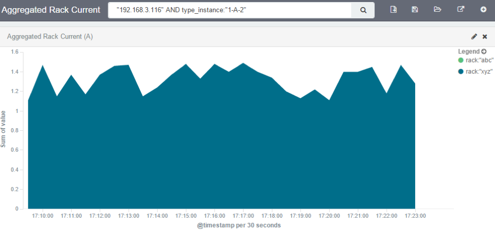
Note: When using area charts to careful to not account for the same measurement twice, by mixing power consumers and power producers, or a Rack PDU’s input and output power.
Creating a Dashboard
Dashboards are a collection of one or more visualizations. They can be changed or new Dashboards can be created. The following steps outline how a new Dashboard can be created.
Click on Dashboard.

Click on the new dashboard icon.

Click on the add visualization icon.

This will show the previously saved visualizations. Click on the visualization you want to add to the dashboard.
Repeat the previous steps until all the desired visualizations are added.
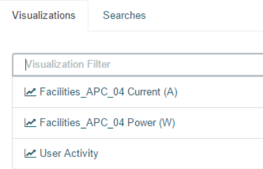
Resize and reposition the graphs as needed.
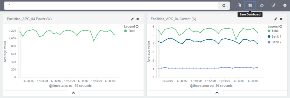
If applicable, filters can be added to the dashboard.
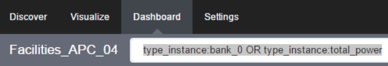
Click on the save icon.

Provide the dashboard name and then click on save.
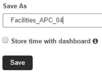
Inspecting a Dashboard
From this point on can be opened and viewed, following the below steps.
Click on Dashboard.
Click on the folder icon.

Click on the dashboard name. It is possible to search for a dashboard by entering a search expression in the dashboard filter.
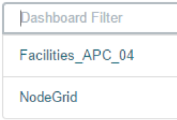
The selected dashboard will show up.
The display time frame can be adjusted by clicking on the clock icon.
Selecting a new time frame.
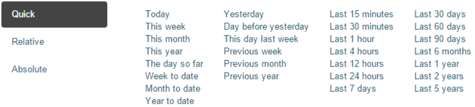
It is possible to automatically refresh the Dashboard by clicking on the auto-refresh icon and selecting the refresh frequency

Applications
The Nodegrid platform allows running additional applications on it. This is mostly used to expand software capabilities like running specific applications close to the end devices. The most common use cases are in the areas of monitoring and SD-WAN. While all Nodegrid units support this feature, is the Services Router Family specifically designed to run applications and provides a wide variety of connectivity options.
Note: The applications feature requires additional licenses to be installed. The Virtualization service is by default disabled and needs to be enabled under
Services
Docker Applications
Docker is an open platform for building, shipping and running distributed applications. The Nodegrid platform allows administrators to run Docker applications. The platform allows pulling of Docker applications from Docker Hub, starting and stopping of the Docker Containers.
Note: "Enable Virtualization Services" must be enabled in Security :: Services in order to run NFV's or Docker apps. Both features require licenses (System :: License).
Note: The management of Docker Applications is currently only available through the WebUI. The WebUI provides a basic interface to manage Docker Containers. For more advanced features can administrators use the docker command line tools.
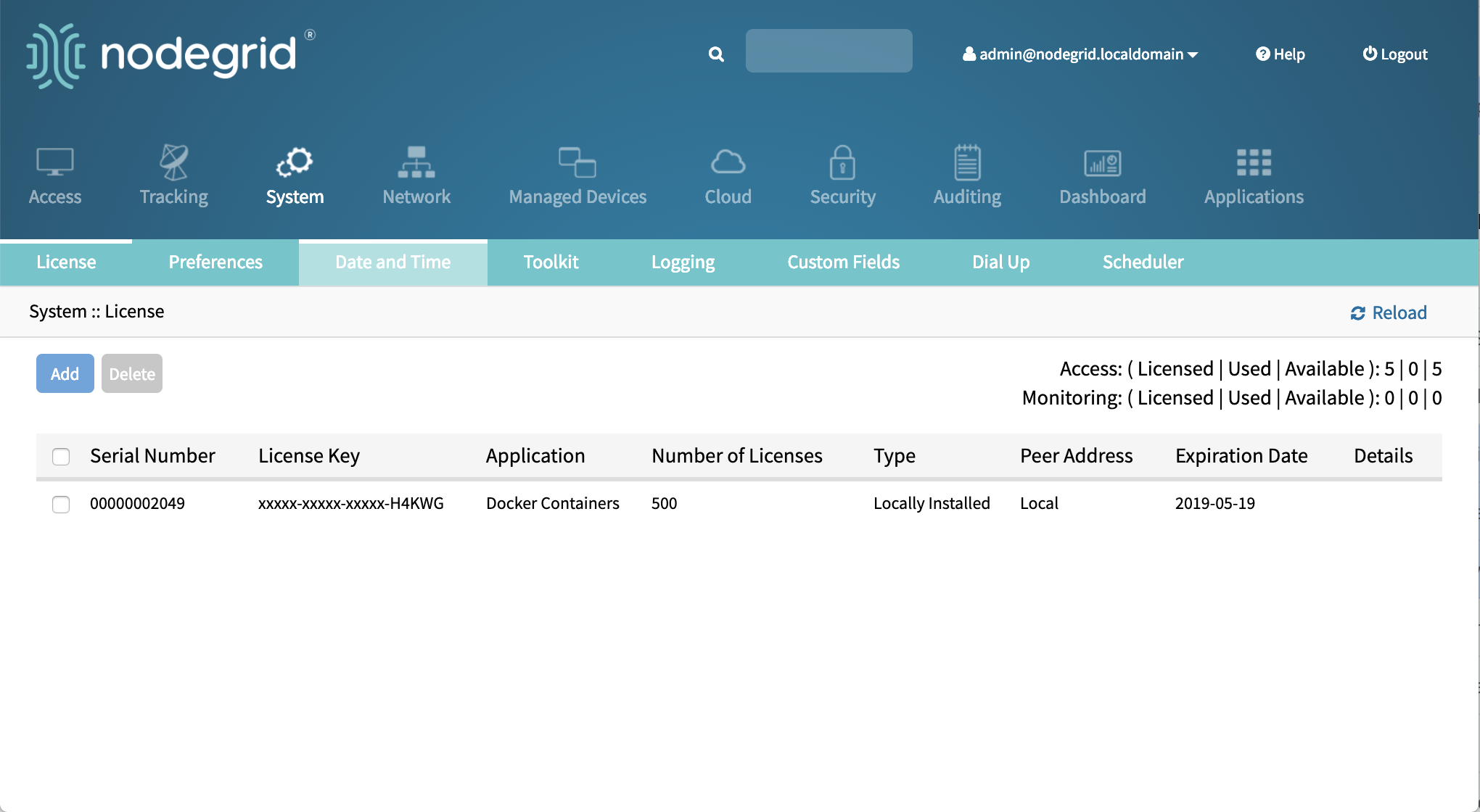
Docker Images
The Applications :: Images section allows administrators to download and to delete specific Docker containers images. They can be directly downloaded from Docker Hub. For this, the Nodegrid requires direct network access to Docker Hub.
New Images can be download following the below steps.
Navigate to
Applications :: ImagesClick on
AddProvide the image which should be downloaded, specific versions can be downloaded by using the
:sign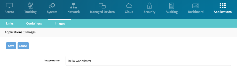
Click on
Save, the image will now be downloaded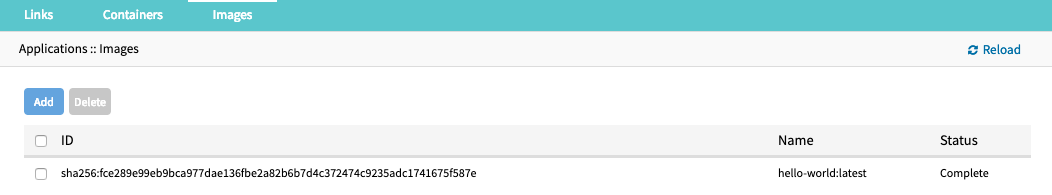
Docker Containers
The Applications :: Containers section allows administrators to add a container based on an existing image to the Nodegrid system. The container can be started, stopped and deleted if required.
For additional detail see the official Docker create documentation.
Note: After the container was created it will not be started automatically.
To add a container follow the following steps
Navigate to
Applications :: ContainersClick on Add
Provide the following information
Setting Value Description Image name name of a Docker Image List of valid image names can be found under Applications :: ImagesCommand Command Optional, command which will be run within the container Hostname hostname Hostname which will be assigned to the container Domain domain name Domain name which will be assigned to the container Container Name Name Name of the Docker container CPUs NUMBER Amount of CPU's which will be assigned to the container Memory(MB) NUMBER Amount of RAM assigned to the container Arguments Arguments Optional, Options which will be used when the container is created
Application Links
Application Links allow administrators to create simple web links to running containers and other applications.
- Navigate to
Applications :: Links - Click on
Add - Provide a
Namefor the link - Provide a valid URL in the
URLfield - Select an Icon as desired by clicking on
Select Icon
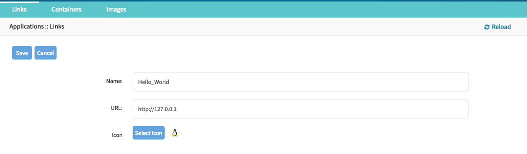
- The link will now be available
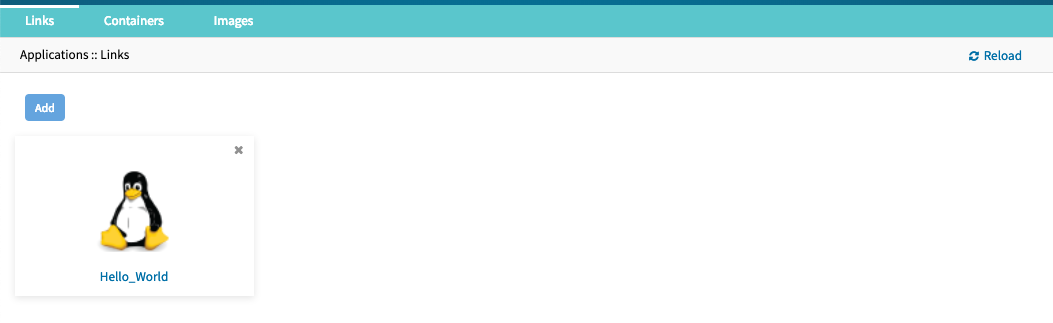
Note: Depending on the Application might it be advantages to create a target device for the created Application.
Network Function Virtualisation
The Nodegrid platform allows administrators to run additional NFV's or other Virtual Machines. A large variety of configuration options is available through the command line interface.
Please contact Technical Support for more information.
Appendix
Technical Support
Our Technical Support staff are standing by to provide assistance in case you have any operational or installation issues regarding your licensed Nodegrid product. In order to be assisted in the fastest way possible, follow the steps below:
- Verify the relevant section of this manual to see if the problem can be solved by following the recommended procedures shown
- Online help documentation, see www.zpesystems.com/support
- Visit our Help Center Website (https://deskportal.zoho.com/portal/zpesystemsinc/kb) for our Knowledge Base and other useful links
Submit a Support Ticket
To submit an online ticket request for support follow the following steps:
- click on
Submit a requestlink on the top right corner of the page. - Enter the required information on the request form. Provide as much detailed information as possible on the description of the problem or question.
- If there is an attachment, add a file or drop the file in the drop area.
- Check the
I'm not a robotcheckbox. - Click on
Submit
You will receive an Email from ZPE Systems confirming that your request has been received and will be reviewed by our support staff. The Email will as well contain your ticket number. Please take note if the ticket number and refer to it at later times as needed.
Updates and Patches
To automatically receive information about important security patch announcements, future firmware updates, and other technical information, sign up to The Loop here:
Configuring Virtual Serial Port (vSPC) on VM Servers
In order to redirect the VMware virtual machine vSPC data to Nodegrid Platform, the virtual machine serial port needs to be configured as described below:
- Go to ESXi configuration (vSphereTM). Select the virtual machine you want to connect and click the Edit Virtual Machine Settings link;
- Click Add. The virtual machine must be turned off;
- Click Serial Manager Device, then click on Next in the pop-up window;
- Click Connect Via Network, then click Next;
- Select Client (VM initiates the connection) – this is the default
- For Port URI, type <group_id> where group_id is an identifier that can be used during the auto-discovery to relate servers of the same group. This field is optional.
- On vSPC URI, type telnet://<IP or Nodegrid Manager hostname>:9977
- Click Finish.
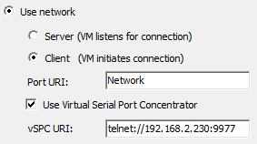
- Finally, make sure that vSPC port is enabled on the ESXi firewall. In order to check that, go to ESXi Configuration, select Security Profile and click on Properties.
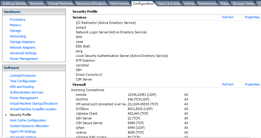
- On Remote Access page, check the box related to VM serial port connected to vSPC. The Outgoing Ports should have a TCP port range starting from 1024 or higher and the port range must include the TCP port used on the vSPC URI field (default 9977).
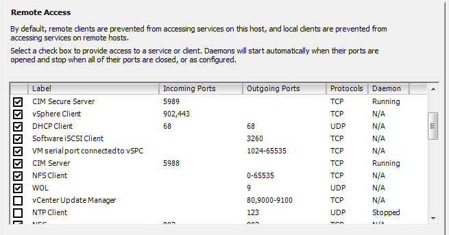
To modify the outgoing port range, connect to the ESXi command line and execute the following commands:

Edit the port section:

Save the changes and then restart the firewall service:

For further information on VMware firewall, please refer to VMware Knowledge Base.
DC Power
DC power is connected to DC-powered equipment using three wires: Return (RTN), Ground (⏚) and 48 VDC.
Warning It is critical that the power source supports the DC power requirements of your Nodegrid. Make sure that your power source is the correct type and that your DC power cables are in good condition before proceeding. Failure to do so could result in personal injury or damage to the equipment.
Warning Wiring to power from a DC supply may be confusing, especially in telecom racks, where the supply's positive wire (usually of red color) goes to the ground, and the hot wire (usually of black color) carries the -48VDC. In case of any doubt, consult a certified electric technician before proceeding with connections. Failure to do the right connections could result in personal injury or damage to the equipment.
Fundamentals
Figure: Dual DC Power Connection Terminal Block
| Number | Description |
|---|---|
| 1 | Power Switch |
| 2 | RTN (Return) |
| 3 | Ground (⏚) |
| 4 | 48 VDC |
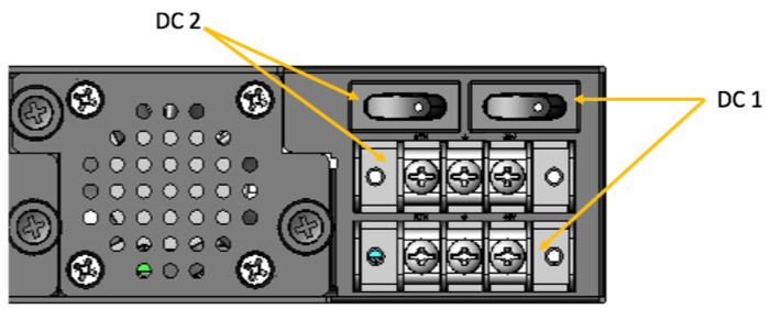
Figure: DC association - terminal power source and switch
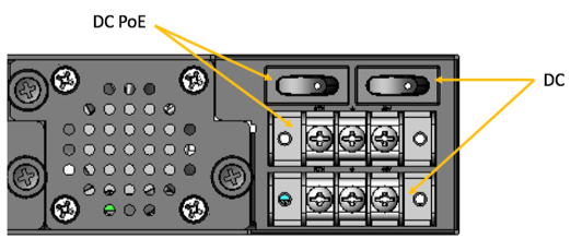
Figure: NSR Single DC + PoE Power Connection Terminal Block
To power a Nodegrid unit with DC power:
- Make sure the unit is turned off.
- Make sure DC power cables are not connected to a power source. Never work on powered wires.
- Remove the protective cover from the DC power block by sliding it to the left or right.
- Loosen all three DC power connection terminal screws.
- Connect your return lead to the RTN terminal, your ground lead to the ⏚ terminal and your 48 VDC lead to the 48 VDC terminal and tighten the screws.
- Slide the protective cover back into place over the DC terminal block.
- If your unit has dual-input DC terminals, repeat steps 3-6 for the second terminal block.
- Connect the DC power cables to the DC power source and turn on the DC power source.
- Connect a serial client (set as 115200 8N1) to the console port (Teraterm, puTTY, etc) (optional)
- Turn on your unit. Double-check booting messages on the connected serial client.
- Turn on the power switches of the connected devices.
- Connect the DC power cables to the DC power source and turn on the DC power source.
- Turn on your unit.
- Turn on the power switches of the connected devices.
Case of -48VDC supply
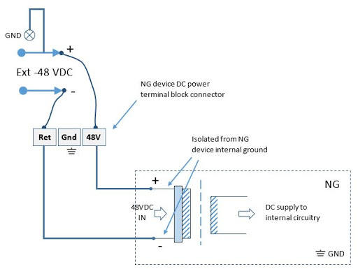
Case of +48VDC supply
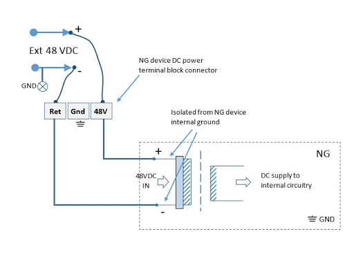
AC Power
AC diagram for the NSR models with PoE+ support
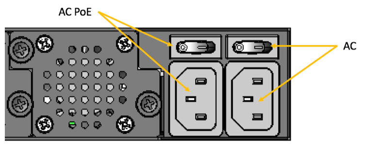
Figure: NSR Single AC + PoE Power Input and Switch
Serial Port Pinout
The tables below display serial port pinout information.
Cisco-like Pinout
| Pin | Signal Name | Input/Output |
|---|---|---|
| 1 | CTS | IN |
| 2 | DCD | IN |
| 3 | RxD | IN |
| 4 | GND | N/A |
| 5 | GND | N/A |
| 6 | TxD | OUT |
| 7 | DTR | OUT |
| 8 | RTS | OUT |
Legacy Pinout
| Pin | Signal Name | Input/Output |
|---|---|---|
| 1 | RTS | OUT |
| 2 | DTR | OUT |
| 3 | TxD | OUT |
| 4 | GND | N/A |
| 5 | CTS | IN |
| 6 | RxD | IN |
| 7 | DCD | IN |
| 8 | Unused | N/A |
Safety
Please refer to the links below for product safety information.
Quick Install Guide
Please refer to the links below for product installation information.
RoHS
Please refer to the links below for RoHS information.
Data Persistency
In normal operation, user data resulting from keystrokes, managed devices output and device monitoring data passing through our product may be stored in nonvolatile device memory when data logging or monitoring is enabled in the configuration settings.
The Nodegrid devices contain the following memory devices:
- BIOS Memory Size: 64MB Memory Type: NOR Flash Volatility: Nonvolatile User Data: No
- Flash Disk Memory Size: 32 GB or 64 GB. Other custom sizes may be used. Memory Type: SSD Volatility: Nonvolatile User Data: Yes. Partition/Data: sda2 - unit configuration sda5 - backup configuration sda8 - user home directories and log files
- RAM Memory Size: 4 GB or 8 GB Memory Type: DDR3 Volatility: Volatile User Data: Yes
There are two ways to remove user data from the nonvolatile memory of Nodegrid unit:
- Soft Removal: removes files and installs factory default configuration on flash disk.
- Hard Removal: completely erases the flash disk. This procedure will destroy ALL data on flash disk and render it unrecoverable even by data recovery services. After that, the Nodegrid software must be reinstalled via network.
Soft Removal
Erase the nonvolatile memory of Nodegrid using the following procedure:
- Shutdown Nodegrid unit and power it off
- Remove Nodegrid unit from the network (disconnect Ethernet cables of the unit)
- Disconnect any USB storage device and USB network device connected to Nodegrid unit
Access Nodegrid unit with one of the following options:
- a. Nodegrid console port using a RJ-45 console adapter and a straight-through network cable connected to a terminal or workstation.
- b. HDMI port and USB port connected to an HDMI monitor and USB keyboard.
- Power on Nodegrid unit and select 'Nodegrid
- Rescue Mode' in the following menu:
- Power on Nodegrid unit and select 'Nodegrid
xxxxxxxxxx*****************************************************************************Nodegrid Manager <version> **Nodegrid Manager <version> - Factory Default Settings **Nodegrid Manager <version> - Rescue Mode <-- **Nodegrid Manager <version> - Network boot **Nodegrid Manager <version> (verbose) ** ** ** ** ** ** ** ** *****************************************************************************
 ` Use the * and * keys to select which entry is highlighted.
  Press enter to boot the selected OS, `e' to edit the commands
  before booting or `c' for a command-line.`
- At the prompt ("bash-4.3#"), run this command to erase all files and load factory configuration, without quotation marks (‘’): 'apply_settings --factory-and-cleanlogs -f -h'
- Wait the following message:
Apply factory settings completed.
INIT: Switching [ ... ] reboot: System halted- Power off the unit.
Hard Removal - Secure Erase
Erase the nonvolatile memory of Nodegrid unit using the following procedure:
- Shutdown Nodegrid unit and power it off
- Remove Nodegrid unit from the network (disconnect Ethernet cables of the unit)
- Disconnect any USB storage device and USB network device connected to Nodegrid unit
Access Nodegrid unit with one of the following options:
- a. Nodegrid console port using a RJ-45 console adapter and a straight-through network cable connected to a terminal or workstation.
- b. HDMI port and USB port connected to an HDMI monitor and USB keyboard.
- Power on the unit
- Press the 'Esc' key after BIOS setup page appears on your screen
- Select 'Nodegrid Platform - Secure Erase' in the Grub Menu:
                             GNU GRUB version 2.00

 +--------------------------------------------------------------------------+
 |Nodegrid Platform - Chain boot                                            |
 |Nodegrid Platform - Rescue Mode                                           |
 |Nodegrid Platform - Secure Erase  <--                                     |
 |                                                                          |
 |                                                                          |
 |                                                                          |
 |                                                                          |
 |                                                                          |
 |                                                                          |
 |                                                                          |
 |                                                                          |
 +--------------------------------------------------------------------------+
  `Use the ^ and v keys to select which entry is highlighted.
  Press enter to boot the selected OS, `e' to edit the commands
  before booting or `c' for a command-line.`
- Type 'erase' to permanently erase all data from the system:
Nodegrid Boot live - Secure Erase
This action will completely erase the system. Using this procedure will destroy ALL data on the SSD and render it unrecoverable even by data recovery services. After executing this step, system software will no longer exist and must be reinstalled via network.
Type 'erase' to secure erase the SSD or 'cancel' to reboot:
Note: Secure Erase requires the unit to be power cycled (powered off and powered on) prior to the erase command. Otherwise, the following message will show and the system will halt to allow the user to perform a power cycle as required:
Operation not supported. Unit must be power cycled prior to erase command.
Wait for system halt and power cycle the unit.
[ 4.614365] reboot: System halted
- Confirming
Secure erase cannot be canceled once confirmed.
Type 'yes' to confirm secure erase:
- Wait for the message 'System halted'.
Secure erase of SDD will start now…
security_password="PasSWorD"
/dev/sda:
Issuing SECURITY_SET_PASS command, password="PasSWorD", user=user, mode=high
security_password="PasSWorD"
/dev/sda:
Issuing SECURITY_ERASE command, password="PasSWorD", user=user
Secure erase completed. System halting…
[ 29.083186] reboot: System halted
- Power off the unit.
Access here for a copy of the Letter of Volatility
Credits
ZPE Systems, the ZPE Systems logo, Nodegrid, and Nodegrid Manager are registered Trademarks of ZPE Systems, Inc. or its affiliates in the U.S. and other countries.
All other marks are the property of their respective owners.
© 2013-2019 ZPE Systems, Inc.
Contact us
Sales: sales@zpesystems.com
Support: support@zpesystems.com
ZPE Systems, Inc.
46757 Fremont Blvd.
Fremont, CA 94538
USA
![]()