Serial Console PDU Management Guide
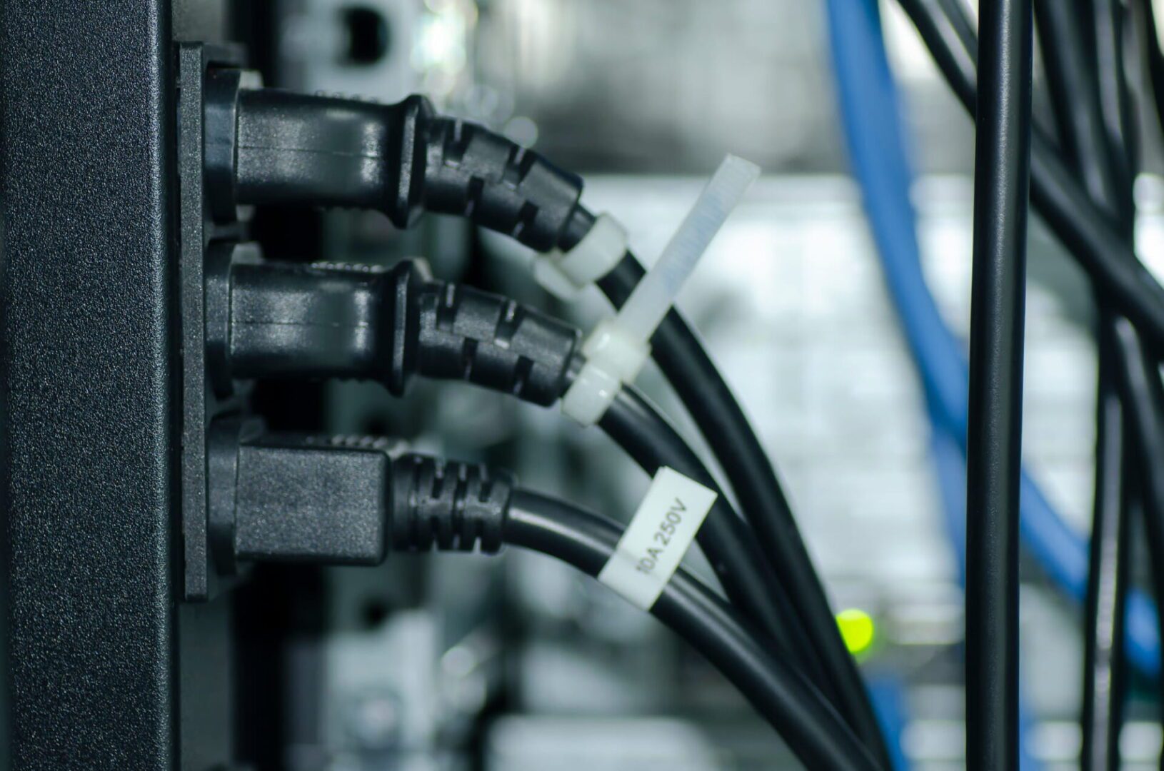
PDUs (power distribution units) control and optimize how power flows to infrastructure devices like servers, routers, firewalls, and switches. PDUs are difficult to manage remotely, for a couple of reasons. First, many aren’t network-connected, so configuring and updating new devices or fixing problems typically requires tedious, on-site work. Those that do have network connectivity tend to lack automation capabilities and integrations with other tools, so they have to be manually and individually managed. In modern enterprise environments with complex, distributed networks, managing hundreds of individual power devices one at a time is extremely challenging.
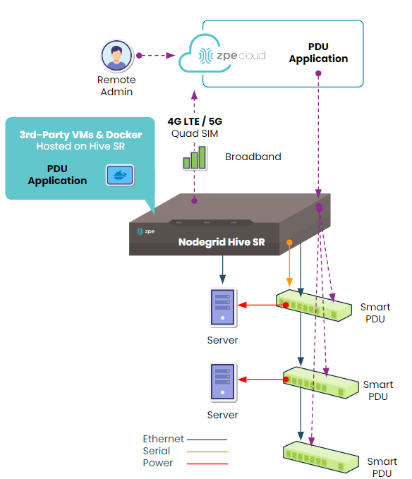
A serial console solves this problem by physically connecting to multiple PDUs and using a dedicated network interface to enable remote PDU management. A next-gen solution like Nodegrid also provides a centralized management platform that teams can use to remotely administer all of the PDUs and other infrastructure devices deployed across the entire distributed network. Plus, Nodegrid has an open architecture that supports third-party power software and automation to streamline infrastructure management and boost operational efficiency.
This guide to serial console PDU management explains everything you need to know to get started with remote power control and automated provisioning using the Nodegrid platform.
Deploying Nodegrid for remote PDU management
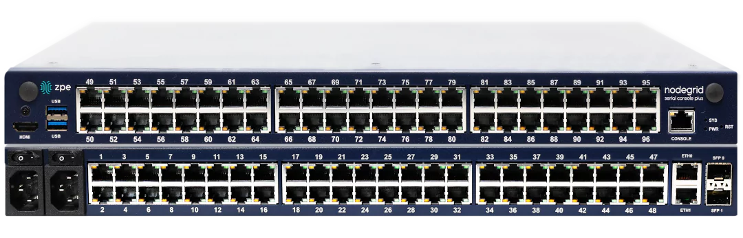
The Nodegrid family from ZPE Systems includes a range of serial consoles and branch routers that are designed for different use cases. They all provide out-of-band management, network failover, and serial console capabilities, but the number and type of interfaces and managed port configurations vary. Critically, all Nodegrid devices can automatically discover power devices from any vendor and provide secure remote access, eliminating the need to manage PDUs on-site.
Nodegrid also has an open architecture that can host or integrate other vendors’ software for PDU management, NetOps automation, SASE security, and more. It gives administrators a single, unified platform to orchestrate both automated and manual workflows for PDUs and other Nodegrid-connected infrastructure at all distributed business sites.
How to deploy the Nodegrid Hive SR for serial console PDU management.
Nodegrid’s out-of-band (OOB) management solution creates an isolated management network that doesn’t rely on production resources and, as such, remains remotely accessible during major outages, ransomware infections, and other adverse events. This gives IT teams a lifeline to remotely roll back PDU firmware updates, power-cycle hung devices, and rebuild infected systems without the time and expense of on-site visits.
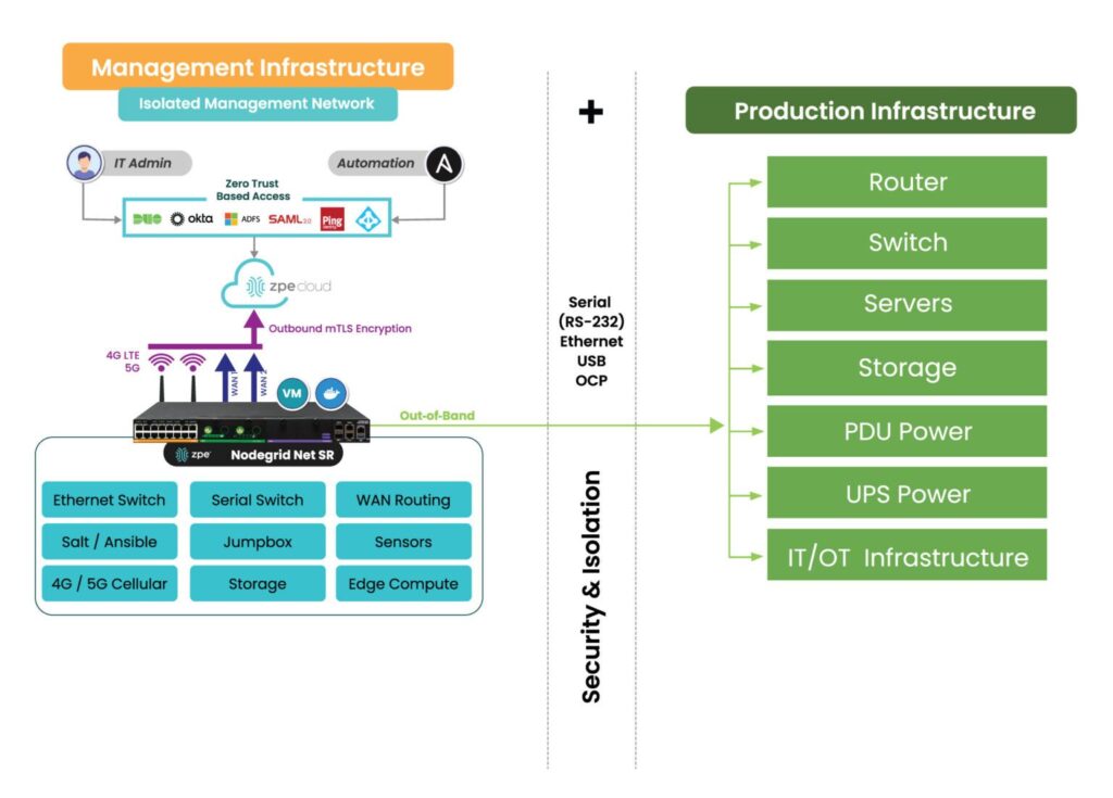
How the Nodegrid Net SR isolates and protects the management network.
Accessing and managing PDUs with Nodegrid
Nodegrid serial consoles and services routers are accessible via the on-premises Nodegrid Manager software or the SaaS ZPE Cloud platform. When connected to the physical console ports on PDUs and other devices, it can provide serial console access and live status messages (such as connected, in-use, and disconnected).
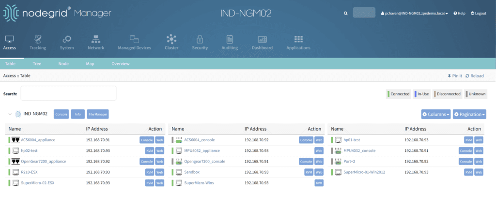
A view of all the equipment connected to a Nodegrid device.
To access and manage a PDU from Nodegrid Manager or ZPE Cloud:
1. Click on the PDU’s name from the access dashboard. The PDU device view screen will appear, as seen below.
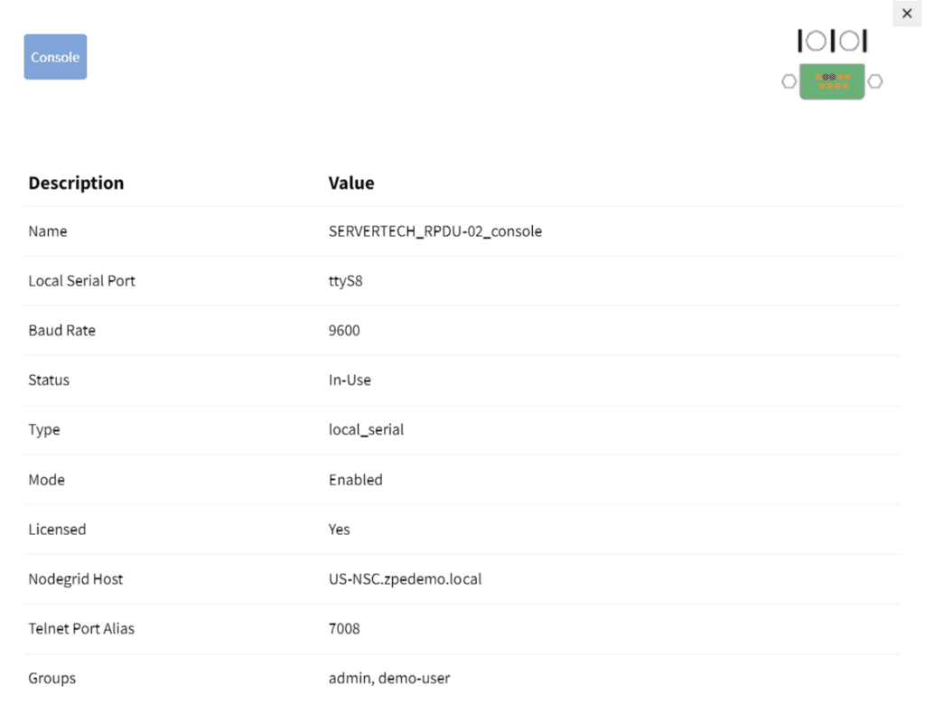
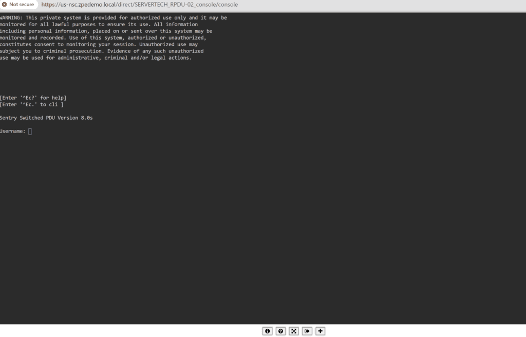
2. Click on the Console tab. A terminal session will open, providing remote console access to the PDU as if you were directly connected.
3. If your PDU is network-enabled, adding it to the Hive SR via IP address provides access to the Web UI from Nodegrid, adding a WEB tab as seen below.
4. Clicking the WEB tab will open the PDU’s web UI.
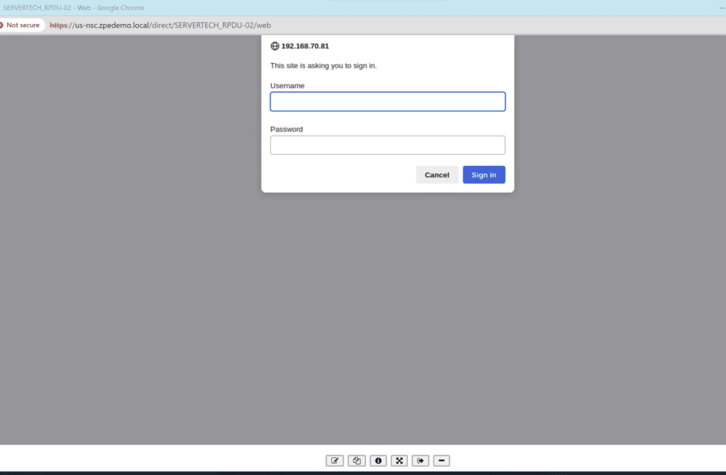
An example of a PDU web UI that will open upon clicking the WEB tab.
Remotely controlling power for individual outlets
Nodegrid can integrate your PDU so that each managed serial port on the Hive is mapped to a specific outlet. Doing so allows users to power individual outlets off and on from Nodegrid Manager or ZPE Cloud. It also enables a continuous console session to the managed device with BIOS-level control during the reboot cycle.
To map a PDU outlet to a managed serial port from Nodegrid Manager or ZPE Cloud:
1. Click Managed Devices from the top menu bar, and then select the Devices tab.
The Managed Devices :: Devices menu.
2. Click the Commands tab, click ADD, and then select Outlet.
3. Select the applicable PDU, tower, and outlet to map to the specified managed serial port and then click Add. A confirmation message will appear in the window below.
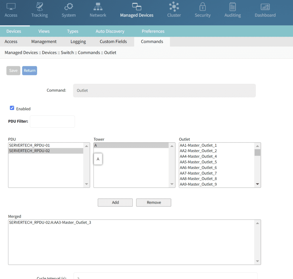
Mapping the selected serial port to Outlet 3 on PDU 2.
To control power for a specific serial port/managed device:
1. Click Access from the top menu bar, and then click the name of the relevant port/device
2. If the PDU has been integrated with that port, the Outlet Status display appears as shown below.
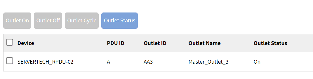
The Outlet Status for the Cisco switch configured on this port and outlet.
3. Depending on the outlet’s present status, certain options will be available:
- Clicking the Outlet On tab will enable an outlet that is powered off.
- Clicking the Outlet Off tab will disable an outlet that is powered off.
- Clicking Outlet Cycle will power-cycle the outlet, turning it off and then back on again.
Implementing automated PDU provisioning and updates
Nodegrid uses zero-touch provisioning (ZTP) to automatically configure managed devices on boot-up. If your PDU is network-connected and DHCP-enabled, like some ServerTech and Raritan PDUs, Nodegrid’s ZTP can automate configurations and firmware updates.
To implement zero-touch provisioning for PDUs:
- Create configuration files tailored to your specific PDU models. These files typically include:
- fwupdate.cfg – required for firmware upgrades
- config.txt – contains specific device configurations
- devices.csv – manages bulk configurations
- Upload configuration and firmware files to the Nodegrid Datastore directory, which acts as a root directory for the integrated TFTP/HTTPS server.
- Configure Nodegrid’s DHCP server to point to the fwupdate.cfg file on the TFTP/HTTPS server.
- Upon their next DHCP renewal, the PDUs will contact Nodegrid’s DHCP server, which will direct them to the fwupdate.cfg file on the TFTP/HTTPS server. The PDUs will fetch these files and perform the necessary configurations or firmware updates. Other configuration options can also be triggered based on vendor-class-identifier settings in the DHCP options.
Nodegrid ZTP includes a magic cookie, a unique identifier stored on the PDU that prevents the repeated execution of the same configuration tasks. If a mismatch between the stored cookie and the new configuration cookie is detected, the device knows to pull fresh configurations, ensuring that updates are only applied when needed.
Want to learn more?
The Nodegrid solution combines serial console PDU management with consolidated network and infrastructure management capabilities for a unified experience and improved efficiency. Download our solutions guide or contact our sales team to learn more about adding a Nodegrid solution to your management infrastructure.

")


